Omega Owners Forum

Please login or register.

Login with username, password and session length
Advanced search  

News:

Search the maintenance guides for answers to 99.999% of Omega questions

Pages: [1]   Go Down

Author Topic: Inside the 2.5TD ECU  (Read 27048 times)

0 Members and 1 Guest are viewing this topic.

prj

  • Junior Member
  • **
  • Offline Offline
  • Gender: Male
  • Estonia
  • Posts: 57
    • View Profile
Inside the 2.5TD ECU
« on: 22 February 2012, 15:52:33 »

Introduction

I want to give people a little overview of what a "Stage 1" tune is and just describe the general approach to chip tuning.

One of my cars is MY2000 Opel Omega-B 2.5TD, and I will use this one as an example.

What makes these cars a little special, is that the engine is lifted from a BMW. It is the intercooled version of M51D25, slightly detuned.
In return, BMW's using this engine are fitted with GM's AR35 automatic transmissions.
However, Opel in their infinite wisdom used the AR25 box on the diesel and the AR35 on their petrol engines. The 25 and 35 are just torque limits - 250nm and 350nm accordingly.

I bought the car with a blown trans for peanuts, and luckily the only difference between the AR25 and AR35 are uprated internals. So I acquired an AR35, retained the torque converter and bell housing from the AR25 and hey presto, I have a transmission that can handle 350nm. After fixing the boost leaks (the intercooler on this Omega was like swiss cheese) the car can be tuned for more torque and power.

First step was to find the ECU and check how boost is controlled.
The ECU turned out to be in the fusebox under the hood, and just slides out. The connector is a typical JPT-55 used in most Bosch applications of the 90-s (remember, the engine was developed in 1991!), and the control unit itself is a Bosch MSA-11 type or in other words - ancient by even 2000's standards when the car was built. Forget any flashing, only the manual approach will lead to results.
Around the turbo there are no fancy solenoids - the boost is mechanically controlled by a spring to about 1.2-1.3 bar.

Inside the ECU

To open the ECU, a series of tabs must be unbent. The rear ones are a bitch, and it will take a while if you are doing it for the first time.
Once the casing is off, two boards are revealed. These boards are connected together by a flat ribbon cable and can be separated at the back, however there are a bunch of T8 and T20 screws that need to be undone for the ECU to come apart:
  • Four T20's under the ECU
  • Four T8's by the connector of the ECU
  • Two T8's inside the ECU under the cover
Once those are off, the entire assembly slides out.

Splitting the two boards reveals two chips soldered to the top board, marked "1 037 355 974" and "1 037 355 975", which contain the software, that needs to be tuned.
Of course, since they are soldered in, they first have to be de-soldered and sockets soldered in ("socketing the ECU").
Both chips are 27c256, 32kb UV erasable EPROM's and the main processors are 8051 derivatives.

Operation of the MSA-11 ECU

Before doing something inside the ECU one needs to understand why every change is made. The operation and algorithms of the ECU must be understood to reach a good result.
Most diesel ECU-s employ a similar control strategy. All the more modern units have their roots in the old MSA ECU's.

There are three primary inputs and one primary output that are linearized (obviously these are not the only ones):
  • RPM - taken from some sort of trigger wheel, this lets the ECU know how fast the engine is rotating.
  • TPS - driver throttle input, taken from a potentiometer at the throttle pedal.
  • Mass flow - taken from a mass airflow sensor, to let the ECU know how much air is entering the engine.
  • Pump control voltage - this is the primary output, which is used to drive the high pressure pump. It is linearized based on RPM and requested Injection Quantity, so that the ECU knows what voltage it has to supply to the pump to get a certain amount of diesel fuel into a cylinder.
Since boost is controlled mechanically, the only thing the ECU controls is when and how much fuel is delivered, and in simplified terms fuel equals torque in a diesel engine.
The fuel injection quantity (or IQ) is based on the driver pedal input, then limited by the MAF to prevent excessive smoke and also limited by a torque limiter to prevent mechanical failure.

As mentioned before, on the hardware side of things there are two main processors. The first processor calculates the required IQ and the second one takes that IQ and interfaces with the pump.
The chip with the lower software number contains all the calibration data and logic for determining IQ (plus a few other things, like glow plugs etc) and the chip with the higher number has calibrations for controlling the pump, including timing of injection start.

Mapping the MSA-11

Now that we have some theory down, let's get down to business.
I only removed the chip containing the IQ calibrations, because the SOI (start of injection) is pretty decently calibrated from factory, and since I am not going to modify the pump voltage map, I have no need to modify these calibrations (more on that later).

After reading the chip in a programmer, the first step is to find the master table. The master table contains the address references of all the other tables and it is a series of addresses.
It's generally pretty easy to find just flicking through the file with a hex editor, or you can write an automated tool that would look for ten 16 bit addresses in a row...

Anyway, the master table for this file is at 0x74D0:


Now we just have to start looking through all the addresses and as a start find the large 3D maps.
« Last Edit: 01 March 2012, 10:17:37 by Jimbob »
Logged

prj

  • Junior Member
  • **
  • Offline Offline
  • Gender: Male
  • Estonia
  • Posts: 57
    • View Profile
Re: Re: Inside the 2.5TD ECU
« Reply #1 on: 22 February 2012, 15:53:30 »

Driver's wish

The first map of interest is the Driver's wish map. This map is for requested IQ by the driver based on RPM and throttle position.
It is located at  0x7DA0. Let's take this map as an example on how to read axes and dimensions of the map.

Here it is in hex form:


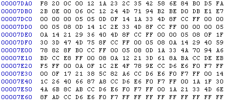
F8 20 is an axis identifier. 20 in this case is RPM. After the axis identifier there is the axis length, which is 0C or 12 in decimal.
After the length are the actual axis values themselves. 12 of them, as the length indicates.
Now comes the next axis identifier - FA 2B. 2B is throttle position, and it's length is 0E or 14.
So what can we conclude from this? We have a map of RPM x Throttle position, with the dimensions of 12 x 14. The only such map in this ECU is the Driver's wish, and it's output is IQ.
Of course you don't always know the axis identifiers. While RPM is usually 0x20 in these older  ECU's, throttle position can vary, but you can also tell the maps apart by their shape.

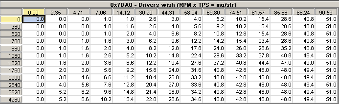
Let's take a look at the map with conversions applied. For RPM this is X*20, for TPS it is X/2.55 and for IQ we have X*0.2 in this ECU.
Here is the map itself in TunerPro:


And in 3D:


Tuning this map allows us to adjust how the throttle reacts. When tuning for performance, the important part is to make sure that enough IQ is requested.
We can see that the last column (>90% throttle opening) always requests 51mg/str. Since 51mg/str is the maximum in this ECU (255*0.2=51), this map does not need to be modified, unless you want to alter throttle pedal behaviour for some reason.
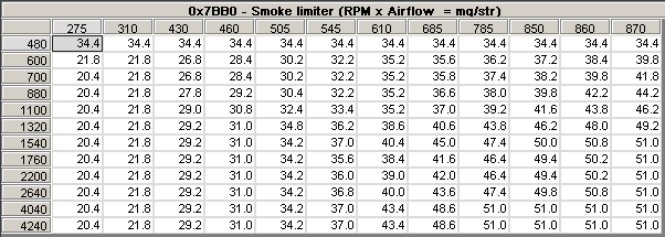
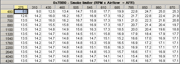
Smoke limiter

The smoke limiter map limits injected IQ based on mass air flow read from the MAF. If we did not have this map, the engine would be flooded every time the driver gave the car a lot of throttle, because there would not be enough air in the engine to combust the fuel.
Why is it called smoke limiter? Because diesel starts to smoke quite a bit when it is running rich, so this map limits smoke among other things.

The map is located at 0x7BB0, it is a 12 x 12 map with the inputs being RPM and Airflow and the output being IQ.
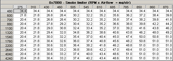
Airflow is also mg/stroke, and the multiplier is X*5
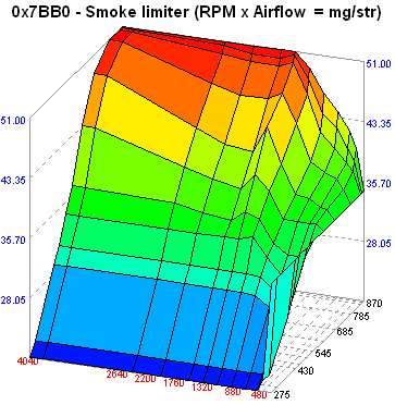
Pictures:


If you think for a moment, you will realize, that this map in reality is an AFR rich limiter.
The Y axis in the map is air in mg/stroke and the output values are mg/stroke as well.
Instead of doing the calculation in your head all the time, let's just change the way we are presented with the data:

This is a lot easier to work with, and makes much more sense.

To tune this map, we need to understand how the car drives. The torque converter lockup is around 1500 rpm on this transmission. The car is very heavy (close to 1900 kg) and the turbo is not of a VNT technology, so there is turbo lag until 1900-2000 RPM.
The biggest problem is response when starting to move from standstill. We can see that the original calibrator saw this problem, and allowed for richer AFR's at the 1540 RPM point, however, at 1760 RPM this is backed off again.

Here is an illustration with the area in question highlighted:


Since the car does not really smoke (only a very light puff) at 1500 RPM, from a performance standpoint there is no real point in backing off max rich AFR at 1760 RPM.
Also, it is possible to add a little more fuel at 1540 RPM as well, to make the car a bit faster off the line.

We can also make sure that the top end (airflow > 850 mg/stroke) is not limited by the map and the ECU can always inject enough. The maximum once again is 51 mg/stroke (255).
The final tuned map looks like this:


Or in AFR mode:


Torque limiter

In this binary there are two of these maps, and they are identical. The map is used for component protection through engine torque limitation.
The maps are located at 0x75E0 and 0x7610, and have 20 values, based on RPM.


When tuning limiters it is very important to understand what exactly you are doing and why.
With the stock automatic gearbox, this map can't be tuned at all. The stock gearboxes barely handle the stock torque (and tend to fall apart), never mind increased torque. But my car's gearbox is not stock, and it is specified to handle 350nm, which this engine will not reach without hardware mods.
Also take note of the end of the map. This map is basically a rev limiter as well. On the stock map the rev limiter is very soft. We don't need it to be as soft, we just need it to be there.

The Omega is rated conservatively as 130 PS, while BMW's with the same engine have 145 PS. The only noticeable difference in the calibration is the torque limiter.
If I remember correctly, BMW's go up to 47 mg/stroke, while this car is limited to 43.

Assuming the gearbox has been upgraded, the map can be set to 51mg/stroke throughout for a nice power increase. This will net about 20 extra horsepower.
Here is a picture overlaying the original limiter and the new limiter.


Because there are two identical maps, both have to be modified.
« Last Edit: 01 March 2012, 10:18:50 by Jimbob »
Logged

prj

  • Junior Member
  • **
  • Offline Offline
  • Gender: Male
  • Estonia
  • Posts: 57
    • View Profile
Re: Re: Inside the 2.5TD ECU
« Reply #2 on: 22 February 2012, 15:53:59 »

The 51mg/stroke limit

As you might have noticed, we are capped at 51 mg/stroke, because this value is 0xFF or 255.
To look at how to get around this, one has to remember how the ECU works.

The mg/stroke conversion (X*0.2) is only there in this amount, because of how the second part of the ECU is calibrated to deliver fuel.
The IQ is only a value that gets passed to the second processor, and if we modify how the second processor sees that value, then we can get higher actual IQ's.

In the second chip is the quantity adjustment map, which tells the ECU the control voltage to reach a certain IQ.
We can either raise only the very edge of this map, so that the low-end calibrations in the first chip remain the same - but that would mean that our IQ is not a linear number anymore, and that makes it hard to tune. Or alternatively, it can be done the right way - the entire quantity adjustment map can be shifted to the left, to obtain a different scaling for IQ in general, but this would mean re-adjusting every map in the IQ calibration.

Either way, both methods require adjusting the injection timing, and over 51 mg/stroke the boost should be raised to reduce EGT, so this is a more involving project on this car - installing a boost controller, boost gauge and recalibrating a lot of maps. There is simply too little to gain for a lot of work in my opinion, but with bigger injectors there is a lot more potential, and it can all be done with the stock control unit.

Conclusion

I hope you learned something about chip tuning by reading this. Of course, most people who "do chip tuning" just copy someone else's tuned files for easy money and never get the understanding of what goes on inside. Blindly trusting a file can easily lead to mechanical failure of components, because you never know if the calibrations have been performed correctly, or if the tuner just randomly raised some maps.
I also did not cover checksumming the files - I guess you will have to find something out on your own ;)
Logged
Pages: [1]   Go Up
 

Page created in 0.039 seconds with 19 queries.