Omega Owners Forum

Please login or register.

Login with username, password and session length
Advanced search  

News:

Please play nicely.  No one wants to listen/read a keyboard warriors rants....

Show Posts

This section allows you to view all posts made by this member. Note that you can only see posts made in areas you currently have access to.

Topics - Kevin Wood

Pages: 1 2 3 4 5 6 [7] 8 9 10 11 12 13 14 ... 20
95
General Car Chat / So you call yourself a motoring journalist...
« on: 01 December 2011, 11:54:24 »
www.youtube.com/watch?v=jSGwsUv49Cg

 :D

Best stick to shopping cars....?
 ;)

96
Omega General Help / MOVED: Autotrader car
« on: 29 November 2011, 09:21:26 »

99
Omega General Help / MOVED: MOT rant..
« on: 30 October 2011, 22:44:11 »

100
.. but a professionally certified one with the tank fitted upside down... That's a first.  :-X

 ;)

101
http://www.pistonheads.com/news/default.asp?storyId=24438&utm_source=newsletter&utm_medium=email&utm_content=html&utm_campaign=2011-10-3

 :-[

Hope the injured guy pulls through. :(

Still, Elite Pete will be pleased to see another couple of BMWs off the road. ;D

102
Maintenance Guides / Fitting variable intermittent wipe
« on: 14 July 2010, 10:49:56 »
This HOWTO has been compiled based on valuable contributions to the forum from NickA, BigAL, Ken T and Welung666 amongst others for which we are grateful.

Later facelift Omegas came with two options regarding intermittent wipers. An optional rain sensor at the top of the windscreen provides variable intermittent wipe automatically. Unfortunately, on cars lacking this option, only a fixed delay intermittent setting was provided.

The manually variable intermittent delay fitted to older Omegas was dropped. The fixed delay is never quite right for the level of rainfall, so it is a worthwhile modification to add variable delay functionality. There are two options, as described:

Retro-fitting a variable delay stalk from an earlier model

This is not too difficult to do. It requires a small modification to the wiring around the stalk and swapping of the intermittent delay timer module.

The first job is to obtain a wiper stalk and timer module from a car with variable intermittent delay. The stalk has an extra thumbwheel in the arm to adjust the delay. This is in fact a variable resistor. On a fixed delay setup, the positive supply is switched via terminal "J" of the stalk via a wire (black with yellow stripe) to the delay module which contains an internal resistor to set the delay. On a variable setup, the variable resistor is inserted into this connection, making the delay variable. The timer module in this instance has a smaller resistor to set the minimum delay, hence the requirement to also swap the timer module to get the correct adjustment range.

To remove the stalk first the steering column cowling must be removed. This is achieved by removing the 3 posidrive screws in the bottom of the cowling and then the 2 countersunk screws in the front of the cowling that are accessible when the steering wheel is turned to the "90 degree" position each side. Unscrew and remove the steering column height adjust lever and remove the upper and lower halves of the cowling.

The stalk can be removed by squeezing the two levers at top and bottom of the switch body and withdrawing it sideways, then withdrawing the electrical connector from the switch body.

103
Maintenance Guides / Repairing a Central Locking Motor
« on: 29 May 2010, 18:58:34 »
Central locking motor failures are a common and irritating problem. Whilst the motors are not too expensive on Trade Club  they aren't exactly cheap either.

The majority of failures are actually caused by the failure of a microswitch inside the motor assembly (it's actually a motor, not a solenoid), and this is cheap and relatively easy to change.

Firstly, the motor must be removed from the car by following the appropriate maintenance guides:

http://www.omegaowners.com/forum/index.php?topic=90504.0
http://www.omegaowners.com/forum/index.php?topic=90543.0

Once the motor is on the bench the black plastic cover needs to be removed, as follows:

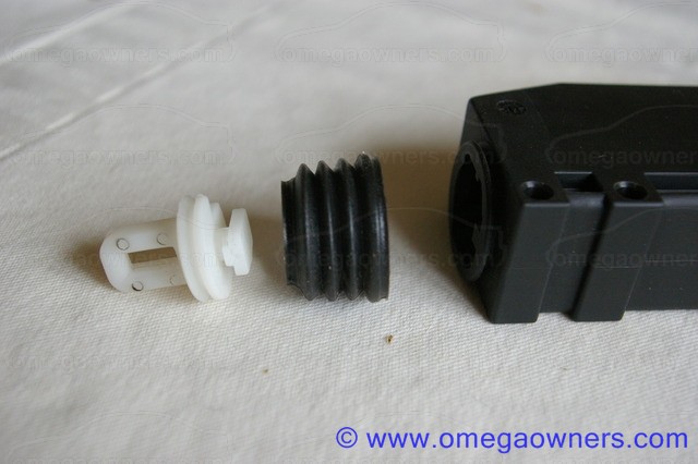
Ease the rubber seal around the actuating lever off the motor body and lever.
Pull the actuating lever out to the fully extended position and remove the protruding part of the white plastic lever from the section that extends into the motor body by sliding it sideways.


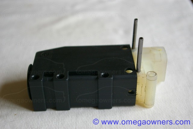
Punch out the 2 roll pins by the lower end of the motor body and carefully prise the black cover past the four lugs surrounding the roll pin holes and off the motor body.


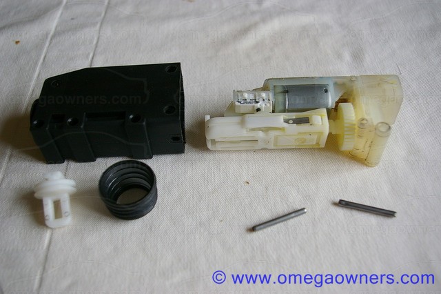
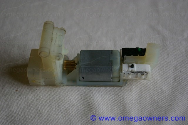
This is what you should see:


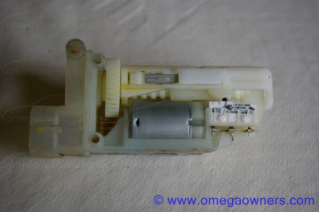
In the following picture you can see the silver motor in the centre with gearing to the left. To the right of the motor is the white microswitch that causes problems. Note that it may not always be white!


In the following picture the mechanism has been stripped down to show the two microswitches in position. Note that passenger and rear doors do not use the second (black in this case) microswitch, and it may not be fitted to the unit at all. The repair procedure is the same. however.


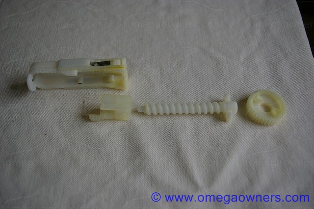
Here is the mechanism that was removed to show the microswitches. A rack is turned by the motor which winds a plastic sled up and down. This sled sits inside the internal part of the lock actuating lever.


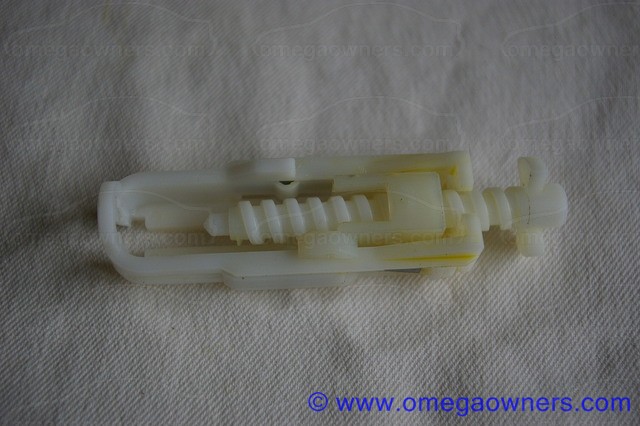
Here is the assembly as it sits inside the motor:


The sled has 3 positions:

It can be wound fully down towards the bottom of the motor whereby it will take the actuating lever down with it and lock the door.

It can be wound fully upwards, taking the actuating lever with it, and unlocking the door.

It can be at a central "parked" position where manual control of the actuating lever is possible, allowing the door to be unlocked and locked manually. When the car is deadlocked, the sled is parked in the fully downwards position, which makes it impossible to manually lift the actuating lever to unlock the door.

It is the microswitch which senses the central position of the sled which causes problems. The purpose of this switch is to cut the supply to the motor as the sled reaches the central position from either above or below. As it wears the contacts become intermittent, and then fail completely, meaning that the supply to the motor is disconnected and the door does not respond to the central locking system.

The microswitch can be tested with a multimeter in-situ at this stage, or one or both of the switches can be replaced as a matter of course. If the rest of the device looks clean, there is no evidence of water ingress or other damage and the mechanism moves freely, it is a fair bet that a microswitch failure caused the problem.

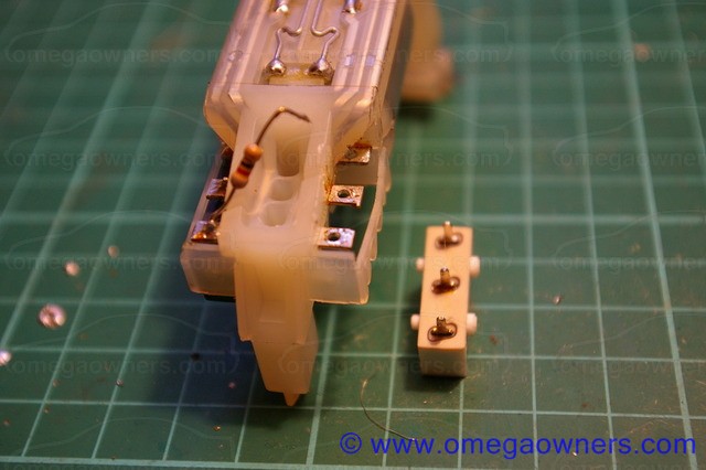
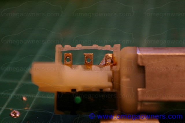
So, on to repairing the motor. To achieve this, the microswitch needs to be removed. It must be desoldered from the connections that are moulded into the body of the motor. The body material has a low melting point, so care must be taken in desoldering to ensure it is not damaged. You will need a desoldering iron or a fairly fine tipped soldering iron and desoldering pump to achieve this.


Once all of the pins have had the solder removed and are free in their holes, ease the body of the microswitch out of the plastic retaining moulding.

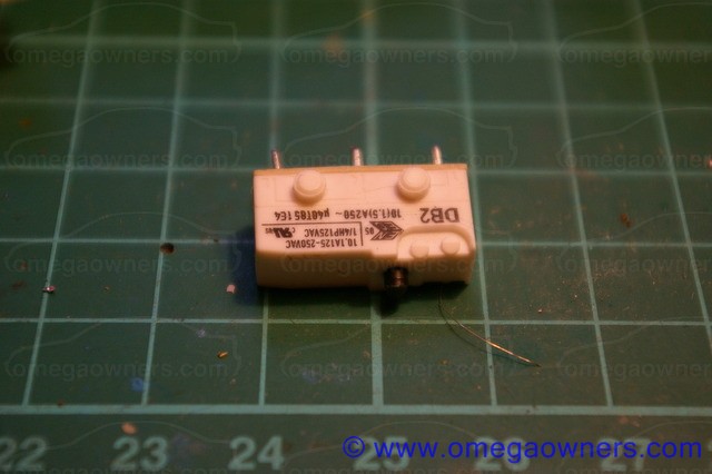
The microswitch is a Cherry type DB2 with button actuator and straight PCB pins (not the solder bucket connections).

RS part number 290-0463, £1.26 at the time of writing looks a direct replacement, as does Farnell part number 1519007, £1.38.

Similar pattern switches are available from Rapid components (78-2410 @ 47p). Note, however, that these do not have the high 10A current rating of the original Cherry switch so might well have a shorter life in this application!

104
Having completed installation of an LPG system, care must be taken in checking correct operation of the system and calibrating it to suit the engine before it is used.

The following is a suggested procedure for commissioning a Stag system installed in an Omega. It assumes as a starting point a completed installation which has not yet been filled with LPG and where the LPG system has not yet been powered up.

1) Check the vehicle still runs on petrol.

With the vehicle completely assembled but the LPG system 12v permanent supply not yet connected (remove the fuse, for example), try to start the engine.

The engine should run exactly as it did before installation, on petrol. If there are any problems at this stage the following should be considered:

  • Have all items disturbed been re-connected correctly? (hoses, electrical connections, etc)
  • Could an air leak have been introduced into the induction system during removal of the manifold?
  • Have the LPG nozzles been connected to the LPG injectors? (otherwise there is an air leak!)
  • Have the petrol injector piggy-back connections been made correctly? (no injector signals swapped between cylinders and all injectors connected)
  • Have the connections to the Petrol ECU been made to the correct pins and are the cable colour codes as expected?

If anything is wrong, back-track your work until you find the problem. If there is a problem running on petrol there's no point proceeding further with the LPG setup until it is resolved.

Now is also a good time to check for leaks in the plumbing to the vapouriser, to ensure that the vapouriser gets hot to the touch, indicating healthy coolant flow, and to top up the coolant level if required.

2) Install the diagnostic software and connect a PC.

The Stag "AC Gas Synchro" software and USB driver should be installed on a laptop. It is better to download the latest version from http://www.ac.com.pl than to rely on the CD that is supplied with the kit. Note that the software version required depends on the exact ECU model fitted.

Connect the diagnostic cable to the 4 pin connector that emerges from the Stag loom, and plug into a USB port on the laptop. Allow the driver to find the USB device.

Load "AC Gas Synchro" software.

Insert the fuse or connect the permanent 12v supply to the LPG system (there may be a small spark due to the inrush current).

Switch on the vehicle ignition and then attempt to connect to the LPG ECU using ACGasSynchro.

At this point, the latest firmware can (and should) be installed onto the LPG ECU.

3) Check the LPG controller configuration using ACGasSynchro.

The ACGasSynchro software should be showing a screen similar to the following:


Note that the above shows the parameters for a Stag 300 ECU. Other variants such as the Stag 300+ and Stag 4 will have variations but the basics (which is all we're currently interested in) are the same.

Set the Car Parameters to suit your vehicle. In all Omegas converted according to this guide, the settings shown will suit, except that the Number of Cylinders and Number of Cylinders for coil should be set according to the number of cylinders on the engine.

The LPG Controller Settings shown should be a good starting point except to note that the Calibration Parameters are automatically set during calibration and should not be edited manually.

Ensure that the Injector Type is correctly set for your LPG injectors. The Valtek Type 30 injectors with red coil housings normally supplied in Teilo's kits should be configured as "VALTEC/RAIL/AC 3 Ohm". Other injector types will require different settings and damage can result from an incorrect setting!

4) Start the engine on petrol and check live parameters using ACGasSynchro.

Verify that the engine still starts and runs normally on petrol.

Check the live data displayed on the right hand side of the screen when ACGasSynchro is running and connected to the LPG ecu.

With a fully warmed up engine running on petrol the following typical values should be displayed:


ParameterTypical value
LPG PressureNot Important
MAP PressureAround 0.30
Injection Time (all cyls)Around 3 ms
LPG Tempshould match ambient temperature of engine bay
RED TempShould match coolant temperature
Lambda VoltageShould cycle between 0 and 1v (0 and 5v for X20XEV)
Battery13-14.5 volts
RPMShould match engine RPM


If the temperature and pressure readings are incorrect it could be that the ECU is configured for the wrong type of sensors. Open the Settings tab and check these match the sensors supplied in your kit.

Injection time should be visible for each of the cylinders in the engine. On a V6, it should be obvious that the injection time for the two banks are varying independently (for example, if the 1,3,5 bank is connected to channels 1,2&3 of the ECU, these should be showing the same duration whereas channels 4,5&6 will be slightly different). This can be useful in identifying injectors that have been cross-wired by mistake.

If the engine RPM is wildly inaccurate check the setting for Number of Cylinders and RPM Signal.

Make sure that any issues are resolved before proceeding further.


105
Maintenance Guides / Fitting LPG - Electrical Connections
« on: 06 April 2010, 10:02:11 »
Connections to the engine ECU and battery

The LPG system needs the following connections from the car's electrical system to supply power to the LPG system, in order to determine the engine operating conditions and also to allow the Lambda sensor output to be available during system calibration:

  • Permanent 12v supply
  • Ignition switched 12v supply
  • RPM (Tachometer) signal
  • Lambda sensor output(s)
In addition to this, the LPG system needs to intercept the signal to each petrol injector in order to determine the time and duration of the injection events and to allow the petrol injectors to be disabled when running on LPG.

For the switched 12v supply, RPM and Lambda sensor signals, the most convenient place to intercept these is probably where the wiring emerges from the engine ECU in the triangular plastic box next to the battery.

An easy way to find the connections is to dismantle the connector(s) which plug into the ECU and to find the numbered pin corresponding to the signal of interest. On the X25XE, X30XE and X20XEV engines it is reasonably easy to solder additional wires to the pins in the connector. On the Z22XE, Y26SE and Y32SE engines, the pin pattern of the ECU electrical connector is too dense and it is better to identify the wire by finding the connector pin, but follow it a few centimetres up the loom before stripping the wire, soldering a connection to it and protecting with heat-shrink sleeving.

The following table indicates on which connector pins these signals can be found for each of the petrol engine options and the colour coding of both the vehicle wiring looms and the Stag LPG system looms:


Engine TypeY26SE/Y32SEX25XE/X30XEZ22XEX20XEV
Signal NameLPG Loom Colour
Switched 12vRed(thin)X86 Pin47 BlackPin27 BlackX84 Pin64 BlackPin17 Black
RPMBrownX86 Pin35 GreenPin43 GreenX84 Pin62 GreenPin20 Green
Lambda Sensor 1VioletX85 Pin28 BluePin28 Brown/BlueX83 Pin57/8 Black/GreyPin36 Yellow
Lambda Sensor 2Violet/GreyX85 Pin44 BluePin47 Brown/BlueN/AN/A

On the Z22XE, Y26SE and Y32SE engines there are two connectors on the ECU and we indicate above which connector is applicable. On the Y32SE/Y26SE X86 is the connector where the loom emerges and heads through the bulkhead into the car interior. X85's loom runs across to the cable tray on the engine.

On the Z22XE, X84 heads to the bulkhead while X83 heads to the engine.

The permanent 12v feed (the thicker of the two red cables in the Stag loom, with an inline fuse holder near the end) can be taken directly from the battery positive terminal. Ensure all other electrical connections have been made before connecting this (or leave the fuse out until you are ready to test).

The ground connection for the LPG system emerges on a thick brown wire next to the permanent 12v feed. this can be connected to the battery negative terminal.

Pages: 1 2 3 4 5 6 [7] 8 9 10 11 12 13 14 ... 20

Page created in 0.03 seconds with 17 queries.