Fitting cruise to a pre facelift.Part numbers are:
Clutch switch 90458543 to chassis S1221920
Clutch pedal switch 90494519 after S chassis
Water pump bracket (cruise) 90469353 (not really the right part)
E-clip for cruise cable 11051532 (come in pack of 10)
Brake switch for cruise 9149766
Basic hand spanners and socket set as well as a cross head screwdriver are about all the tools you need. The electrical wiring should already be in place.
You will need to obtain a control stalk, actuator motor, mounting box, the control cable and the metal carrier end on the cable if your car does not have the additional hole for the cruise cable. The standard kit you find on E-bay looks like this.

The control stalk should look like this.

Note the extra buttons to
I increase or set,
R resume and switch
O off the cruise. Sometimes a brake switch is included in these assorted kits but not always.
You need to get the combined motor/control unit which is fitted under the bonnet, connect the cable coming from the motor to the throttle housing, then install the replacement stalk, and fit a new 4-pin brake switch (not always necessary, depends on your car) and a clutch switch.
Wiring locationNormally on the offside turret top, plugged into a holder.
 Fitting the control stalk
 Remove the control stalk cowling. It's in two halves, separated horizontally. The bottom half is secured to the car with 3 crossheads in triangle pattern underneath, the top half is secured to the bottom half with two crossheads on front face. Screws are under plastic covers, not visible until steering wheel turned through 90 degrees to the left and right. No need to remove the steering wheel as instructed by the Haynes manual. The steering column adjuster stalk on the left side of the column unscrews to allow removal of bottom half casing.
Stalk and switch body slides out after pressing in side retaining clips. Wiring plug held in with grey slide. Remove slide and release plug.
Fit replacement stalk which has one extra little plug on a flying lead. The additional socket is tucked away beside main socket. Fit retaining slide and slide main switch body back in until it locates.
Re-fit cowling. Getting the rubber boots to locate properly can be a bit fiddly so take care.
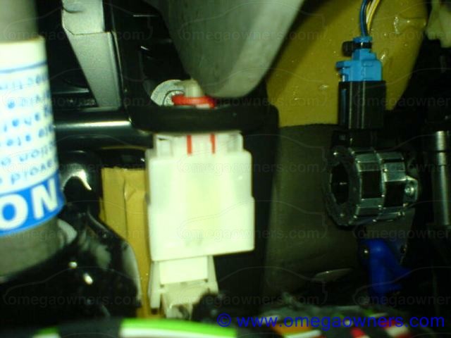
Pedal switchesAccess to the pedal switches can be achieved after the large foam sheet thing is removed. The black plastic holding plugs need a quarter turn anticlockwise to remove.
Brake switches There are two types.
A 2 pin looks like this VX part number 90460325 for petrol models (90458542/90563455 for diesel)
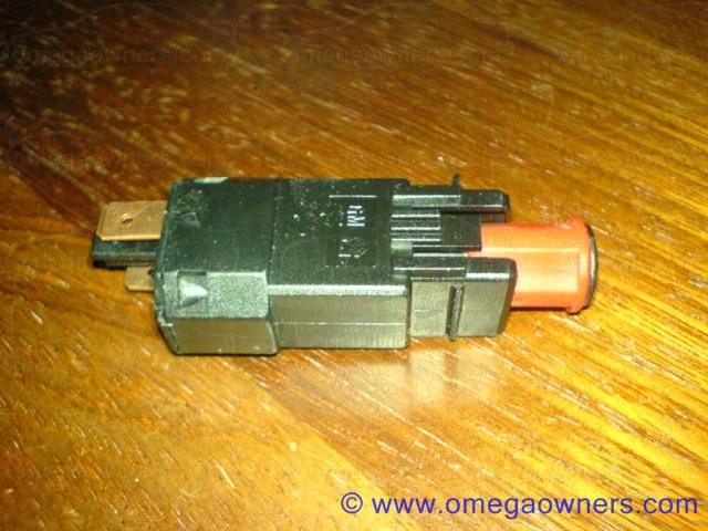
and
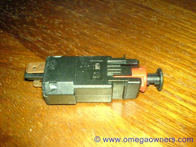
but for cruise operation, you will need a 4 pin switch VX part number xzxzxzxzxz - irrespective of whether you drive a manual or an auto. Some cars have a 4 pin switch as standard. If you do, congrats!! CAUTION - On all switches, there is a red plastic part that moves. Check out the two pictures above. This is like a locking mechanism which prevents the release of the locking tangs to allow the switch to be removed. Take a look at the switches when in place and you will see similar. These need to be moved outwards, away from the switch body, to allow the switch to be removed. If you don't, the switch may well break and you will be far worse off.
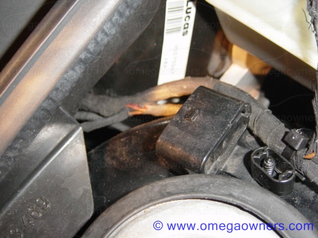
Note the largish cylindrical bit nearest the connection. If it looks like this, you are lucky, do nowt else in this area, other than the clutch switch, if manual. It looks like this when in place.
 Clutch switch wiring
The clutch switch wiring is normally taped up next to the brake wiring loom. Its a white connector and two of the opposite corners of the plug are 'chamfered'. This corresponds with the connection on the clutch switch. When in place, it looks like this with the wiring connector beneath the bottom of the switch.
If you are fitting brand new switches ('cos the clutch switch is not fitted as standard and is as rare as rocking horse poo at the scrappies) then take care not to play with them before fitting.
CAUTION - There is a green plastic keeper fitted from the factory to prevent the depression of the switch prior to fitment. Once removed there is a sort of ratchet mechanism in the switch so that, on first depression, it assumes a 'working' position. If you play with it before fitting and do this early, it is an absolute bu**er to locate as the moving plastic bit (as in the two pin switch) moves, preventing the depression of the locking tangs. Ask me how I know....
Brake switch fitting The brake switch locates in the furthest away (highest) of the two square cut outs on the brake


 Author
Topic: Fitting prefacelift cruise howtoo (Read 14120 times)
Author
Topic: Fitting prefacelift cruise howtoo (Read 14120 times)