Items required:
Set of small torx screwdrivers
Small wire cutters and strippers
Long nose pliers
Small flat bladed screwdriver
Allen keys
Double DIN removal tool
Fine tipped soldering iron and solder
One small capacitor to block DC on each signal line to be provided (1 to 22 uf, 16v)
Length of miniature screened audio cable
Connectors of choice for output cable (female phono line socket)
The procedure is as follows:
1) Disable code protection on the unit (optional).
I found it convenient to disable code protection on the CCR2006 before starting work. This is because I knew the unit would be in and out of the car a couple of times during the procedure and because I wanted to test it on the bench (without the MID connected!) once modified. I suspected that entering the code without a MID would not be easy.
The code can be disabled by powering up the unit with AS held down until a beep is heard, then using buttons 1,2,3 and 4 to change each of the digits displayed until the displayed code matches that on the car pass. Finally, AS should be held down once more until a beep is heard.
Removal of the code can be verified by powering up the radio and checking that "CODE" does not appear on the MID.
2) Remove the CCR2006 from the car.
The CCR2006 is secured with the usual arrangement of a cage in the car into which the head unit clips. A double DIN removal tool is required to release the clips and allow the head unit to be removed. Before this may be used, however, a small allen key should be used to unscrew the small grub screws that cover the four removal tool holes in the fascia of the CCR2006.
With the screws removed, insert the removal tools until they are felt to engage with the clips on the CCR2006 then withdraw the CCR2006. It may be too tight a fit to pull the CCR2006 out using the tools alone. In this case, it may be possible to ease it out by carefully placing a finger and thumb in the cassette and CD changer openings, being careful not to pull on the plastic fascia, but the more substantial frame of the radio behind it.
Double DIN removal tools are available from Halfords for the Vauxhall radios. If a tool is not available it is possible that one could make do by inserting drill bits or allen keys of appropriate diameter but with a greater risk of damaging the clips on the radio chassis.
3) Remove the top cover
The CCR2006 has the appearance of two single DIN boxes bolted together. The upper box contains the radio, cassette and power amplififers whilst the bottom box contains the CD changer. We require to remove the top cover from the upper box only.
The top cover is secured only by metal tags around the edge of the cover. These engage in grooves in the side casing and the cover can be eased loose of the side casing by working round the cover and levering it up using a flat bladed screwdriver.
Put the top cover aside once it has been removed.
4) Remove the cassette mechanism
The cassette player mechanism sits on top of the part of the main circuit board which we need to access so unfortunately it must be removed. It is located by four torx headed screws and connects to the main PCB via two multi way connectors.
The following picture shows the approximate location of the screws and connectors:
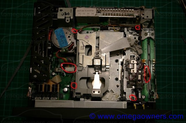
Gently prise away from the main board the connector with multi-coloured ribbon cable located just in front of the cassette motor. There is a second connector on the opposite side of the cassette mechanism adjacent to the head. This has a brown paxolin extension which should be gently eased upwards to release it from the main circuit board.
The four screws which must be removed are at the four corners of the mechanism as pictured.
Once unscrewed, it is helpful to pull forward the rewind and fast forward buttons on the fascia while simultaneously lifting the rear of the cassette mechanism and withdrawing it from the chassis.
Put the cassette mechanism aside somewhere safe (wouldn't it be awful if that stopped working!).
5) Identify the Gain / Tone control IC.
Having removed the cassette mechanism the IC of interest can be seen. It is located right beneath where the cassette motor was located before the mechanism was removed. It is in a 28 pin package bearing the part number TDA7313N.
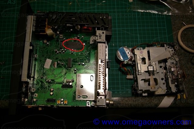
The function of this IC is to select the correct audio signal from the CD, cassette, Tuner or external car kit, apply a variable gain to the signal to allow the volume level to be adjusted, filter the signal as required by the settings of the bass and treble controls, split the two channel signal into front an rear pair and to adjust their individual volumes based on the balance and fader control positions. In short, this IC does most of the processing of the analogue audio signal in the CCR2006. The four analogue outputs from this IC are the line level feeds to the internal power amplifiers and it is these we need to connect to in order to bring out an external line level signal. The pin assignments for these signals is as follows:
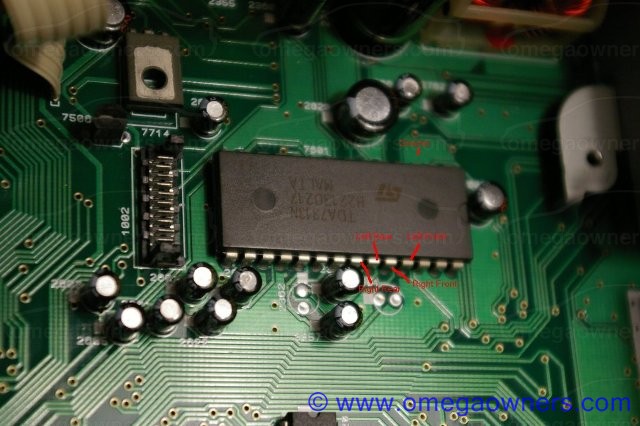
Left Front Pin 25
Right Front Pin 24
Left Rear Pin 23
Right Rear Pin 22
Pin locations are as shown in the following picture:
It is possible to bring out all 4 of these signals although I chose to connect just the front pair. I figured that I would either use the internal amplifier for the rear door speakers or, in the event that I decided to connect them to the external amplifier, do away with the fader control for simplicity.


 Author
Topic: How to fit line level outputs to a CCR2006 (Read 17802 times)
Author
Topic: How to fit line level outputs to a CCR2006 (Read 17802 times)