Omega Owners Forum

Please login or register.

Login with username, password and session length
Advanced search  

News:

Welcome to OOF

Pages: 1 ... 32 33 34 35 36 37 38 [39] 40 41 42   Go Down

Author Topic: Mechanic School Blog  (Read 95947 times)

0 Members and 1 Guest are viewing this topic.

Webby the Bear

  • Omega Queen
  • *****
  • Offline Offline
  • Gender: Male
  • Northampton
  • Posts: 12722
    • 2000 (W Reg.) 2.5 V6 CD
    • View Profile
Re: Mechanic School Blog
« Reply #570 on: 08 May 2013, 18:45:27 »

Having looked at it again I've probably been unclear on what i'm confused about...

I get that the steering wheel turns and the box turns this motion in to backwards and forwards motion.... this will then ''pull'' the arm forward therefore turning left and then it'll push it backwards therefore turning right.

I just don't get how that steering turning motion is physically turned in to that lateral motion.  the little bubble on the right highlighting the roller just doesn't make sense to me  ::)
Logged
RIP Paul Lovejoy

Nick W

  • Omega Queen
  • *****
  • Offline Offline
  • Gender: Male
  • Chatham, Kent
  • Posts: 10856
  • Rover Metro 1.8VVC
    • 3.0l Elite estate
    • View Profile
Re: Mechanic School Blog
« Reply #571 on: 08 May 2013, 22:16:19 »

You might find it easier if you find a diagram of how the Omega steering linkage works.
Then you can apply the knowledge to the solid axle in your diagram. Although you're unlikely to see one on a car unless you start working on '30s cars, or modern trucks.
And after that, you could look up a 'cross steer' solid axle, which is different again!

At least a rack is easy to figure out.
Logged

Marks DTM Calib

  • Administrator
  • *****
  • Offline Offline
  • Gender: Male
  • West Bridgford
  • Posts: 33839
  • Git!
    • View Profile
Re: Mechanic School Blog
« Reply #572 on: 09 May 2013, 13:13:46 »

Thanks Andy. So can I just clear something up cos everyone uses different names for stuff  ;D.........

is what ive called the ''drag link'' the steering idler?

I'm not that well up on the terms myself  :-\ but I think the drag link is the bar that connects the arm from the steering box to the idler arm  :-\

Yes, in the case of the Omega where effectively the drag link and track rod are a combined assembly

If you consider a Land Rover, its the arm from the steering box to the near side track arm (which is part of the hub)
Logged

Marks DTM Calib

  • Administrator
  • *****
  • Offline Offline
  • Gender: Male
  • West Bridgford
  • Posts: 33839
  • Git!
    • View Profile
Re: Mechanic School Blog
« Reply #573 on: 09 May 2013, 13:20:01 »

Having looked at it again I've probably been unclear on what i'm confused about...

I get that the steering wheel turns and the box turns this motion in to backwards and forwards motion.... this will then ''pull'' the arm forward therefore turning left and then it'll push it backwards therefore turning right.

I just don't get how that steering turning motion is physically turned in to that lateral motion.  the little bubble on the right highlighting the roller just doesn't make sense to me  ::)

have a look at a diagram for a recirculating ball steering box (as per the Omega).

Have a little look at this its as simple as it gets (much more complex with power assist etc!)

http://www.howstuffworks.com/steering3.htm
Logged

Entwood

  • Omega Queen
  • *****
  • Offline Offline
  • Gender: Male
  • North Wiltshire
  • Posts: 19566
  • My Old 3.2 V6 Elite (LPG)
    • Audi A6 Allroad 3.0 DTI
    • View Profile
Re: Mechanic School Blog
« Reply #574 on: 09 May 2013, 13:25:38 »

Another good write up here ...

http://www.carbibles.com/steering_bible.html
Logged

Webby the Bear

  • Omega Queen
  • *****
  • Offline Offline
  • Gender: Male
  • Northampton
  • Posts: 12722
    • 2000 (W Reg.) 2.5 V6 CD
    • View Profile
Re: Mechanic School Blog
« Reply #575 on: 09 May 2013, 19:20:38 »

MDTM/Entwood, thanks for those posts; I looked for the ehow and how stuff works but couldn't find it  :-[

Anyways I've found this pic of the underbody front of the omega (2.0L so I am assuming its the same steering system)


so. no. 8 is the track rod, no. 7 is the steering idler/drop arm that transfers the movement from the steering box to the track rod and I presume the steering box (i.e, the gearing attached to the steering shaft) is just above no. 7?

 :y
Logged
RIP Paul Lovejoy

Webby the Bear

  • Omega Queen
  • *****
  • Offline Offline
  • Gender: Male
  • Northampton
  • Posts: 12722
    • 2000 (W Reg.) 2.5 V6 CD
    • View Profile
Re: Mechanic School Blog
« Reply #576 on: 09 May 2013, 19:26:54 »

...oh and where would the pitman arms be in this pic of the omega..... or doesn't it have them?  :)
Logged
RIP Paul Lovejoy

TheBoy

  • Administrator
  • *****
  • Offline Offline
  • Gender: Male
  • Brackley, Northants
  • Posts: 105932
  • I Like Lockdown
    • Whatever Starts
    • View Profile
Re: Mechanic School Blog
« Reply #577 on: 09 May 2013, 19:32:02 »

8 is centre tie rod

6 and 10 are track rods

9 is steering box and pitman arm

7 is steering idler
Logged
Grumpy old man

Webby the Bear

  • Omega Queen
  • *****
  • Offline Offline
  • Gender: Male
  • Northampton
  • Posts: 12722
    • 2000 (W Reg.) 2.5 V6 CD
    • View Profile
Re: Mechanic School Blog
« Reply #578 on: 09 May 2013, 19:40:23 »

Thanks TB,

Shouldn't the steering box be up above the steering idler though as that's below the drivers position, therefore the steering shaft would come down from there?  :-\

 :y
Logged
RIP Paul Lovejoy

TheBoy

  • Administrator
  • *****
  • Offline Offline
  • Gender: Male
  • Brackley, Northants
  • Posts: 105932
  • I Like Lockdown
    • Whatever Starts
    • View Profile
Re: Mechanic School Blog
« Reply #579 on: 09 May 2013, 20:11:42 »

sorry, yes, for rhd swap 7 and 9  :-[
Logged
Grumpy old man

Webby the Bear

  • Omega Queen
  • *****
  • Offline Offline
  • Gender: Male
  • Northampton
  • Posts: 12722
    • 2000 (W Reg.) 2.5 V6 CD
    • View Profile
Re: Mechanic School Blog
« Reply #580 on: 09 May 2013, 20:22:38 »

cheers mate, I think it makes sense now.

I presume when replacing idler, box gears etc they'd be quite a straight forward job? ive checked out the guide. looks quite easy  :-\
Logged
RIP Paul Lovejoy

Webby the Bear

  • Omega Queen
  • *****
  • Offline Offline
  • Gender: Male
  • Northampton
  • Posts: 12722
    • 2000 (W Reg.) 2.5 V6 CD
    • View Profile
Re: Mechanic School Blog
« Reply #581 on: 13 May 2013, 21:53:40 »

Evening guys, how are we???

Well we've had our suspension systems theory and if i'm honest its quite involved and as I want to update on alternator and starter practical tonight I thought id go through the suspension systems for front and then rear.

FRONT SUSPENSION SYSTEMS:

MacPherson Strut:
damper housed in spring coil. at the top it attaches to the strut towers in the engine bay. at the bottom it connects to the hub assembly:

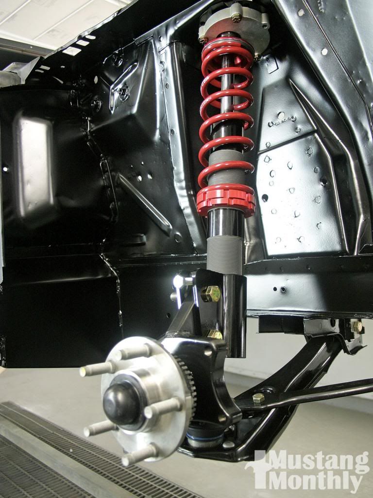
I believe this is the most common type of front suspension on modern cars.

Double Wishbone:
wishbone attached at the top of the hub assembly. a wishbone attached to the bottom of the hub assembly. spring and damper lives between the two. fully independent i.e. moves independently of the other strut on the other side.

Double Link and Radius Arm.
I don't know much about this; all I got is one picture in my assignment  :-[ simply looks like two rods attaching to the hub assembly  :-\ :-\ :-\ anyone confirm that?

REAR SUSPENSION:

Rigid beam axle:
coil springs housing dampers so struts affectively. big hunk of metal connecting the rear hub assemblies ( I think Richard Hammond once described this set up on a 2005 mustang as ''a whacking great gurder with two wheels on the end). non-independent

coil spring and semi trailing arm:
this is fully independent with springs and dampers. there appears to be like two triangular plates that attaches to a subframe allowing everything to pivot and flex. drive shafts coming out of the diff not attached in any way to the suspension. this, I believe is what the omega utilises.

finally the coil spring and leading arm:
separate springs and dampers attached to the car via a beam attached to the diff. 4 metal rods attaching to the car. again don't really have much info on this.

Where does the torsion bar come in to this? obviously all the ones ive highlighted have springs and dampers. are these ever utuilised in addition to springs? I assume not. is the torsion bar an old system?


ok so now some photos  :) :) :) :) :) :) :)
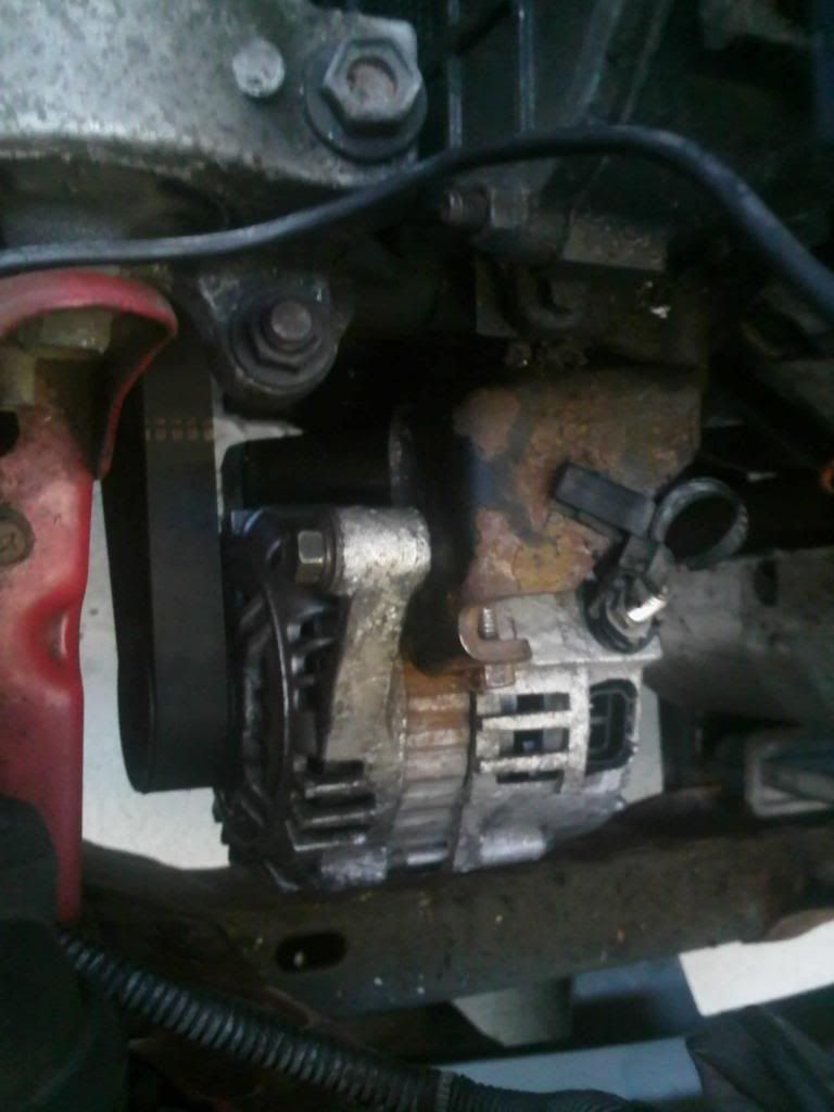
when removing an alternator the order goes like this:
...disconnect battery
...disconnect electrical connections to alternator
...remove drive belt
...remove alternator


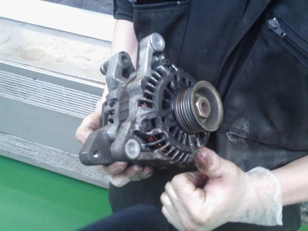
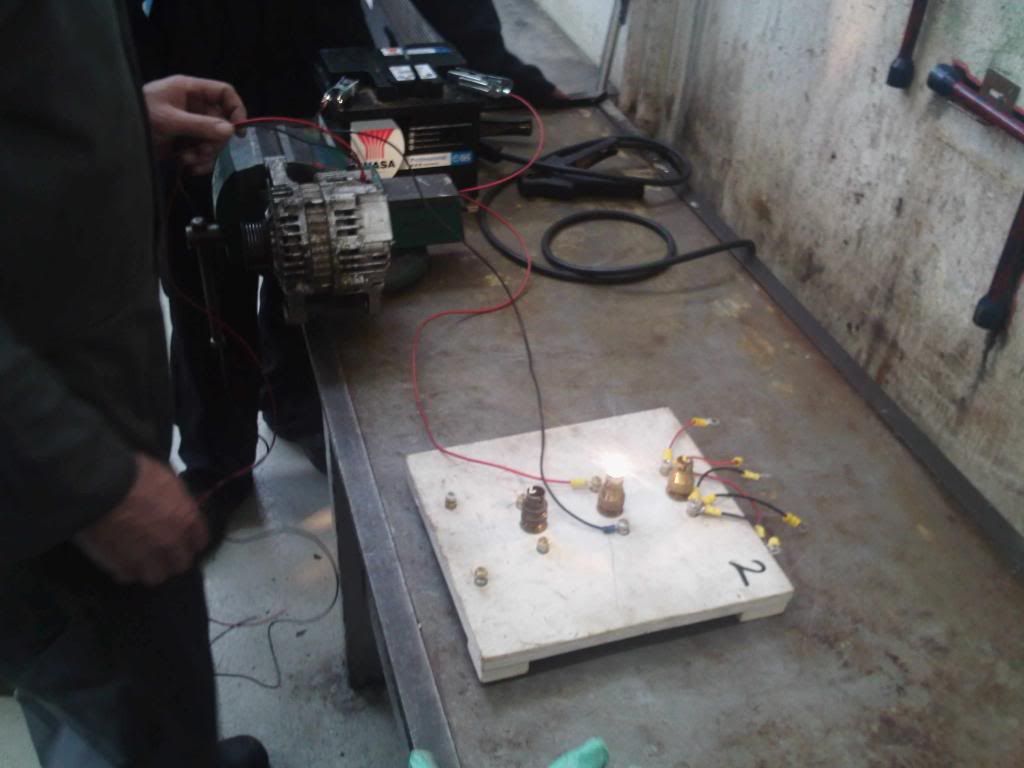
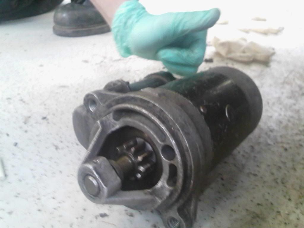
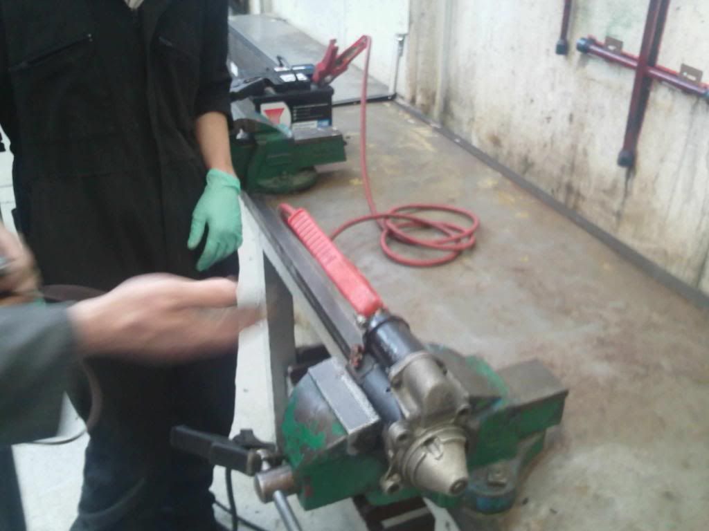
the following is a pic of us testing the alternator whilst off the car....the alternator takes a live from the battery and earths (grounds  :-\ :-X :D) due to its connection to the block. it then has another live lead coming OUT of the alternator which distributes the electricity it produces.
to test whilst off the car...... hook a battery up to the live connection and earth where it would connect to the block. then hook up a circuit to the distribution line with a bulb in it. use a buzz gun to spin the alternator and watch the bulb light up  :) :) :)
testing it on the car would just be a dynamic test... hook your DVOM up to the car whilst its idling. presumably leave for a few minutes and ensure it doesn't drop below 13.8-14.5v.


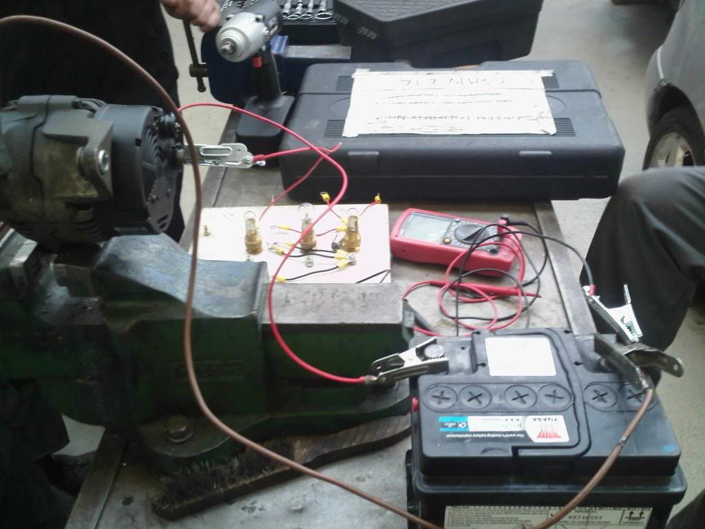
the following is a shot of the tensioner system that's part of the alternator. you loosely fit the alternator in [place and loosely fit the belt, then the bracket in the middle of the pic... you screw the bolt in and as the bolt tightens it pushes against the bracket which in turn forces the alternator outwards and tightens the belt :)
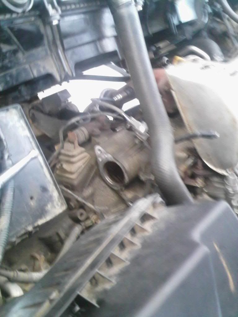

STARTERS:

In short when the ignition key is turned it completes the circuit to the starter. the solenoid creates magnetism and that in turns spins the mechanical motor. this is splined to the flywheel and turns it to start the combustion process (which then ''takes over'').

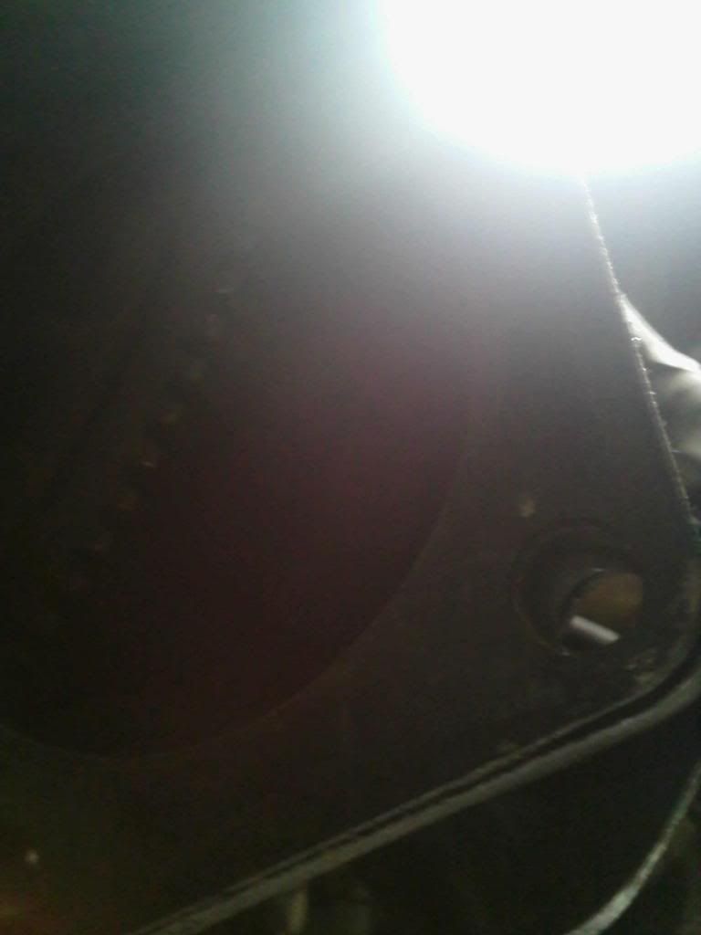
in this shot you can see the cog that turns the flywheel.


the hole where the starter lives. I tried to take this shot so you could see the flywheel inside... not oo sure if you can see it tho  :-\


testing a starter off the car... hook up a battery positive to the part that normally receives the live. and a batt. negative to where it normally touches the block. then hook up a wire/alligator clip to the electrical connector. and touch the live with the other end. motor will engage and spin.


was a really good day. hope you enjoy the update and as ever comments & constructive criticism always welcome  :y :y :y
Logged
RIP Paul Lovejoy

Webby the Bear

  • Omega Queen
  • *****
  • Offline Offline
  • Gender: Male
  • Northampton
  • Posts: 12722
    • 2000 (W Reg.) 2.5 V6 CD
    • View Profile
Re: Mechanic School Blog
« Reply #582 on: 14 May 2013, 20:12:21 »

Word up. My dogs :)

Awesome day at school today. You may have seen my post regarding my indicators not flashing. Well I located the flasher relay, it wasn't clicking when indicators were activated so I replaced it and they work. Took both relays in to school today to test them. Quite interesting as this is a 3-pin relay. This is the relay (not the actual one but similar):


me and the teacher looked at the wiring diagram and worked out that pins 31 and 49 (iirc) were the trigger circuit.... 49a was the high amp circuit. we hooked it up to a battery and it was dead! good one worked great :)

Anyway as I've maintained my lead on the other kids in terms of work done we got to do some electrical diagnosis on lighting systems. really good fun and I'm really loving the electrical diagnosis part.

anyway this brings me back on to electrical diagnosis  ::) I now think i'm in a position to explain myself a bit more and i'm going to (3rd time lucky) explain what I would do in the case of some FACTORY FITTED parking semsors (generic, not omega).

so I pull the wiring diagram for the parking sensors and I find this..... (ive drawn trhis myself... a simplistic look at a saab diagram):


so this is what I would do :)

So, from a diagnostic point of view we would check the simplest thing first: debris on the outside of the sensors as this can affect it's performance. 
 
Fuse next as it's the next easiest to check and is located (from what I could gather rom the Saab forum) in the fusebox in the front passenger compartment. While there we can check the fusebox connection where the fuse plugs in to.
 
If that's good then we would go to the sensors themselves; disconnect and do a resistance check. Also check for any visual signs of a bad sensor.
 
If they're good then we can check for voltage coming to the sensor by activating the sensors, connecting our DVOM to the connector. Then connect the other lead on our DVOM to a known good ground. If no voltage there is a short somewhere which we can trace back.
 
If voltage present then we could go for the beeper, then the control module. I assume the beeper would also be a resistance check and possibly hooking up to a battery off the car to see if it beeps? And then finally replacing the module if everything else tests good?

now I know that wiring diagrams don't provide diagnostic detail but they do include every component youd need to check in order to diagnose a fault.

comments welcome  :y
Logged
RIP Paul Lovejoy

Entwood

  • Omega Queen
  • *****
  • Offline Offline
  • Gender: Male
  • North Wiltshire
  • Posts: 19566
  • My Old 3.2 V6 Elite (LPG)
    • Audi A6 Allroad 3.0 DTI
    • View Profile
Re: Mechanic School Blog
« Reply #583 on: 14 May 2013, 20:21:02 »

The Omega system as fitted by VX has its own built in test system, when powered and good it will make a single beep on selecting reverse, if any sensor is faulty it will emit a continuous beep.

Makes diagnosis easy ... if there is no beep on selecting reverse either a) speaker dead/disconnected  b) no electrics to ECU (fuse/wiring ??) c) ecu FUBAR

If the continuous beep occurs there is a test plug that can be removed, then by counting the beeps that occur it will tell you which sensor(s) is (are) at fault.

:)
Logged

Webby the Bear

  • Omega Queen
  • *****
  • Offline Offline
  • Gender: Male
  • Northampton
  • Posts: 12722
    • 2000 (W Reg.) 2.5 V6 CD
    • View Profile
Re: Mechanic School Blog
« Reply #584 on: 14 May 2013, 20:26:16 »

Cheers Entwood.... that's pretty easy then and definitely a score for GM. And makes sense why you advised me last time to research the exact system you're looking at before going straight to a wiring diagram.

If however, like in the Saab example above that there's no easy diagnosis with the test plug and all you have is the wiring diagram.... would my way be best?

 :)
Logged
RIP Paul Lovejoy
Pages: 1 ... 32 33 34 35 36 37 38 [39] 40 41 42   Go Up
 

Page created in 0.035 seconds with 18 queries.