Omega Owners Forum

Please login or register.

Login with username, password and session length
Advanced search  

News:

Search the maintenance guides for answers to 99.999% of Omega questions

Show Posts

This section allows you to view all posts made by this member. Note that you can only see posts made in areas you currently have access to.

Messages - Perplexer

Pages: [1]
1
Omega General Help / Re: Engine temperature gauge at over 100C
« on: 14 October 2017, 11:52:17 »
Thermostat was replaced 3,5 years ago which was 4000 km ago (I don't drive the car a lot).

Tehmerature when driving .... that's hard to say. The temperature light DID come ON on two occasions while I was city driving (110C). However yesterday it did not. It hovered between 97 and 100 (perhaps due to a bit colder weather now). But when I parked the car, I left it running to see what would happen. And sure enough, after a minute or two the temperature on the dashboard reached 110C and the temperature symbol came on. At about that time the two fans started spinning (at half-speed to my eyes/ears) and the temperature went down to perhaps 98C. The fans stopped after only 20-30 seconds and then the temperature rose to 110C, and the cycle repeated.

It's all very confusing.

2
Omega General Help / Re: Engine temperature gauge at over 100C
« on: 14 October 2017, 00:31:53 »
I checked the GM EPC (Electronic Parts Catalogue) and found that the upper 2-pin thermo switch (Part No. 90242277) has an XC marking (which I confirmed by looking at it) and the lower 3-pin (double-thermostat) switch (Part. No. 90376209) has an WM marking on it (I couldn't confirm that by looking but I kinda trust it to be true).

I then Googled the specs for thermo-switches with XC and WM markings and found that the 2-pin "XC" ones have a temperature range of 100C-95C (for example Wahler 6031.100D) and 3-pin ones have two temperature ranges, one from 105C-100C and one from 120C-115C (for example Hella 6ZT 007 835-151). I'm guessing the upper 2-pin one activates "stage 1" at lower temps (100C) and the lower 3-pin one activates stages 2 and 3 at higher temps (115C and 120C).

That would mean that my XC switch turns on the fan in stage 1 at 100C and turns it off at 95C. But, like I mentioned, when I did a test a few years ago when everything was working, I clearly heard the fan come on at 95C or 96C. Not sure how that's possible if it should only come on at 100C with "XC" type switch.

Confused.

3
Omega General Help / Re: Engine temperature gauge at over 100C
« on: 13 October 2017, 19:38:08 »
I got the coolant temperature sensor (sender for the dashboard) replaced today and while the readings are a bit smoother than before, the needle does still climb to 100 C and over. At around 110 C both fans (radiator fan + AC condenser fan) start spinning, with what I would call half-speed. I read on-line that this is the fan "stage 1". "Stage 2" should be when the radiator fan spins at max speed and "stage 3" should be when both fans spin at max speed and the AC compressor is shut down. At least that's what I read online at various forums.

If that is accurate then it means that my "stage 1" cooling only activates at 110 C which is way too late. Both fans spin for maybe 20 seconds and then stop, and the temp drops to around 97C, and then climbs again to 110C, and the cycle repeats. This is weird because I would expect "stage 2" to kick in at 110C and I would assume "stage 1" was just "missing".

Now I'm not sure which of the two thermo-switches I need to replace on the radiator, the upper 2-pin one or the lower 3-pin one? Which one is responsible for the proper 95C "stage 1" colling activation ?

Thanks.

4
Omega General Help / Re: Engine temperature gauge at over 100C
« on: 01 October 2017, 02:15:30 »
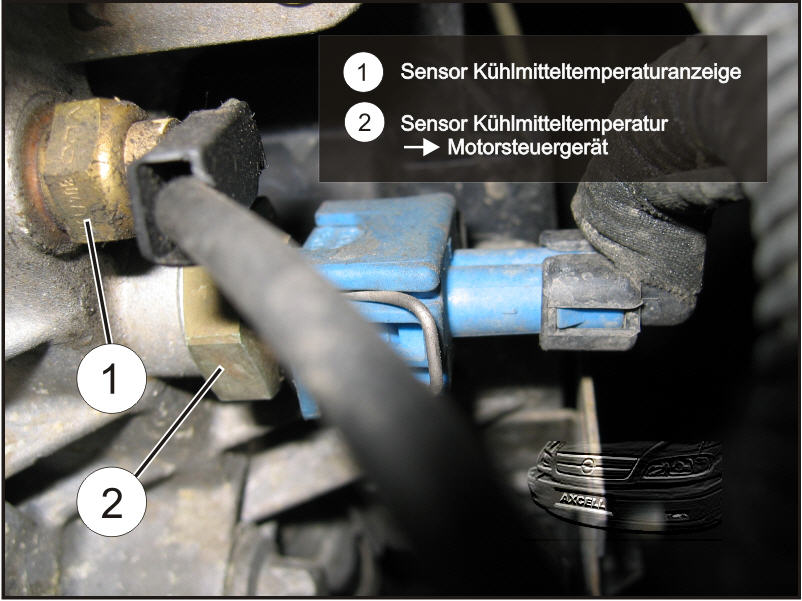
I guess you're talking about the sensor for the dash gauge shown as (1) in this picture:


Can it be that this sensor/sender still "works" but is just showing wrong temps? What would be the way to determine if it's working correctly? To compare it with the reading that the sensor for the ECU (pictured as (2)) is sending? I guess I would need a scan tool to read that temperature (which I don't have), right?

So since I don't have a scan tool to compare sensor (1) and (2) temperatures (if they even can be compared like that), what are my options? Start with buying sensor (1) first or one or the switches on the radiator first (in case the one responsible for activating "stage 1" is bad and has a delay) ?

From what I described it seems that the "stage 1" fan cooling does kick in, but way too late ... or maybe it's at the right time but the sensor for the dash is just displaying skwed temps and it's really 96C and not 105+C. Could that be a possibility ?

5
Omega General Help / Engine temperature gauge at over 100C
« on: 30 September 2017, 20:20:35 »
Hello.

I am having problems with the engine temperature in my car so I need some help.

My car:
Opel Omega B, year 1998, 5-speed manual transmission, automatic climate control, 2.0 16V X20XEV engine.

Problem:
The temperature gauge in the dashboard regularly goes to over 100 Celsius and the red temperature
symbol lights up. A few years ago when everything was working correctly, I have tested the cooling
fan activation temperature, and it was at 95C-96C. Unfortunately I didn't check whethere both fans
were spinning then or if just one was spinning. I also don't know if it was spinning at full speed
or half-speed. But I know it turned on at cca. 95C-96C.

So I decided to do this test again today to see what is happeninb. AirConditioning was turned OFF !

I turned on the car in my driveway and left it running. After about 10-15 minutes, the temperature
reached 95C. Then it was slowly rising by 1 Celsius every 1 minute and reached cca 97C-98C. The fan
still didn't turn on. Then the temperature jumped from 98C to max. (100+C-105+C) in only 5-10 seconds and
the red temperature symbol came on. Then after 15 seconds both fans (main cooler fan + AC fan)
started spinning, but I think only at half speed because it didn't look very fast to me. Is that
"stage 2", since both fans are spinning, or is it "stage 1", since they are spinning slow?

They were spinning for maybe 10-15 seconds and then they turned off. But the temperature gauge
in the dashboard was still on 100+C with glowing red symbol. I then turned off the car.

So now the question is ... is the reading in the dashboard wrong (temperature sensor displaying
wrong temperature?) or is there something wrong with the fan switches? The coolant is fresh, level is
good and there are no leaks anywhere.

Since I know that the main fan turned on at 95C in the past, it looks like "stage 1" is not activated
anymore at 95C. Or it is activated, but only later at 100+C. I'm not sure whether it is stage 1 or stage 2
because both fans start to spin, but they seem to spin slow. I'm not sure how it should be.

I used some contact cleaner on the two temperature switches on the front (on the radiator, top one
with 2-pins and bottom one with 3-pins) but it didn't make any difference. I didn't check/touch the
temperature sensors behind the engine because I could not get to them.

How do the two temperature switches in the radiator work exactly? Are they in direct contact with the coolant?
Are they controlled by the coolant temperature or by the temperature sensors behind the engine? If I wanted
to replace the two temperature switches on the radiator, would I need to drain the coolant out first ?

What are the correct "stages" ?

Stage 1: radiator fan half-speed?
Stage 2: radiator fan full-speed + AC fan half/full?

Has anyone investigated this before ? Any tips on what I should try next would be appreciated. Thanks.

Pics for reference:


6
Omega General Help / Re: Sunroof with a mind of its own
« on: 23 April 2012, 01:21:55 »
If that doesn't work, try checking this thread:

http://www.omegaowners.com/forum/index.php?topic=101646.0

7
"Phantom roof" problem isn't related to the battery being disconnected and the roof needing to be reset.

See this thread:
http://www.omegaowners.com/forum/index.php?topic=101646.0

8
Omega General Help / Re: electric sunroof problem
« on: 23 April 2012, 00:26:27 »
There's a guide about cleaning the magnet disk at http://www.omegaowners.com/forum/index.php?topic=90674.msg1155649#msg1155649 but I don't think that's causing the "phantom roof" problem. You have to disassemble the actual control potentiometer and clean the slideway there as well as respring the metal contacts. I have not done this myself yet but I will in the next few days. It should be an easy job.

Here are a few pictures:
http://users.volja.net/grebenm/omega-b/sunroof/pic1.jpg
http://users.volja.net/grebenm/omega-b/sunroof/pic2.jpg
http://users.volja.net/grebenm/omega-b/sunroof/pic3.jpg
http://users.volja.net/grebenm/omega-b/sunroof/pic4.jpg
http://users.volja.net/grebenm/omega-b/sunroof/pic5.jpg

9
Here are my own measurements on an Opel Omega B 2.0 16V year 1998 with the following equipment:

- X20XEV gas engine
- manual transmission
- central locking
- 4 x electrical windows
- 4 x airbag
- sunroof
- automatic 2-zone airconditioning
- aftermarket Pioneer radio
- NO car alarm
- NO rear sunscreen
- NO rear leveling

Here are two measurement steps I took with stage-by-stage results (the two are actually very similar, you will see the difference yourself in steps 8 and 9):

Measurement 1:

1.  car off, key extracted, doors closed (0.03 A)
2.  insert key (0.03 mA)
3.  turn key to position I (0,13 A)
4.  turn key back to position 0 (0,13 A) (I did this just to see what would happen, you can skip this stage)
5.  turn key to position II (contact, system wakes up) (fluctuates roughly between 3.0 A and 8.0 A)
6.  turn key back to position I (30 to 60 seconds at 0,80 mA because the system is still awake; when it goes to sleep it drops to 0.23 A)
7.  turn key to position 0 (still 0.23 A)
8a. extract key (0.13 A)
9a. open and close door (open door: 1.26 A; when closed, 5 seconds at 0.78 A since cabin lighting is ON, then drops to 0.03 A)

Measurement 2:

1.  car off, key extracted, doors closed (0.03 A)
2.  insert key (0.03 mA)
3.  turn key to position I (0,13 A)
4.  turn key back to position 0 (0,13 A) (I did this just to see what would happen, you can skip this stage)
5.  turn key to position II (contact, system wakes up) (fluctuates roughly between 3.0 A and 8.0 A)
6.  turn key back to position I (30 to 60 seconds at 0,80 mA because the system is still awake; when it goes to sleep it drops to 0.23 A)
7.  turn key to position 0 (still 0.23 A)
8b. open and close door (open door: 1.34 A; when closed, immediately drops to 0.13 A because cabin light goes OFF instantly since key is still in)
9b. extract key (drops to 0.03 A)

0.03 A (which is 30 mA) is that ideal/normal idle current draw a car like this should have. All the measurements were done on the 20 A setting
on the multimeter which means that miliampere measurements are only exact to within one-hundredth of an ampere. 0.03 A displayed on the multimeter can
therefore mean 30 mA or 39 mA. The actual exact value is somewhere in between. I did not do an exact mA measurement since this was exact enough.

So what is important to note is that if I park the car, turn it off, then exit it and leave the key in the ignition, the current drain will stay
rather high at 130 mA which is over 4 times as much as if I remove the key completely ! This test was carried out on a cold car that has been parked
for days. It is possible that if the test was carried out on a car that just returned from a drive and was still hot, the ammount of time after which
the system goes to sleep would be higher than 30 to 60 seconds. The current the system draws while awake could also be higher than 0.8 A since some
additional sensor could be active which was not active in my case when the car (engine) was cold. For example some temperature sensor controlling
and deciding whether the big fan in front of the engine should run again or not. I would imagine she system could keep this sensor active for longer
than 60 seconds after the car was turned off in hot summer days and that would also use more current. Whether the car doors were locked or not was
apparently not important in my case. Perhaps that would be important in the car had a car alarm in which case it would use more current when locked
because the alarm would be active.

Again, these are the measurements on my particular Omega but yours should be very similar. The idle drain should be around 30 mA to 50 mA on a
high-end Omega with car alarm. Anything over that, especially over 120 mA would mean something is wrong. Either something doesn't turn off or some
relay is bad or the computer control unit is bad (doesn't tell the relay to switch the circuit off after 60 seconds or so).

I also checked my alternator while I was at it. I connected my voltmeter to the battery which read 12.4 V when connected to the car and the car was off.
Then when I cranked the car, voltage momentarily dropped to 10.3 V. That's still OK. If it would drop bellow 10 V, or to around 9 V or less, that
would mean that although the battery still has good voltage (12.4 Vor even 12.7 V), it does no longer have enough power to do it's job in the car.
It is probably old and needs to be replaced. After the car was running, the voltage went up to 14.25 V. That's the voltage the alternator is putting
out to recharge the battery. When I turned on the lights it dropped to 14.14 V and when I turned on the airconditioning it dropped to 13.95 V.
So that would be the voltage my alternator was at when I was driving around. It's actually pretty good, especially since I mostly take short drives
in the city. Otherwise the alternator voltage should be between 13 V and 14 V.

Hope this info helps you guys.

10
Maintenance Guides / Cleaning windscreen washer system (pictures)
« on: 25 October 2009, 13:21:08 »
I have prepared a few pictures to go with the "Cleaning windscreen washer system" guide at
http://www.omegaowners.com/forum/YaBB.pl?num=1152616577

Administrator will probably want to move this post under the original guide to make it more complete (and move the images to the server).

Omega B 1998 2.0 16V, LHD, windscreen washer only model (without headlamp washer).

A view of the windscreen washer system hidden behind the front fender (reservoir and the pump still installed):


Windscreen washer pump (you don't need to disconnect the wiring harness and water hose unless you intend to take the pump completely out of the car):


Windscreen washer pump:


Windscreen washer pump:


Windscreen washer pump and the black water hose attached to it. Make sure the rubber where the hose is attached to the pump has not decayed too much as this may very well cause leaking.


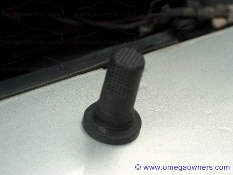
Rubber grommet and the hole it normally sits in when it is installed:


Rubber grommet (which also acts as a filter preventing dirt particles from being sucked into the pump). Ideally you should always make sure you have clean filtered water and/or cleaning agent when you pour them into the reservoir:


Rubber grommet:


Rubber grommet:

11
12. First spray some carbo cleaner into the opening on the solenoid and shake it. Repeat this a few times and wipe clean the dirt that comes out as you go. Do the same with the idle control valve. Spray in some carbo cleaner, use your fingers to plug the holes and shake well so that all the dirt dissolves and runs out. Repeat that until you get clean spray come out of the valve and you don't see any more dirt inside, then wipe it dry. Now do a thorough job on the throttle valve / throttle body itself. Clean the whole mechanism and all the holes leading inside it (like for example that vaccum hose for the tank vent valve). Throttle body itself is not that critical but the throttle valve does need to be thoroughly cleaned. I used an old tooth brush, cotton sticks and anything I could use to do a really good cleaning. You can lubricate the springs on the throttle body with WD40. By the way, please DO use the carburator cleaner spray for the cleaning job and not WD40. I did a test and tried both and I can tell you straight that carbo cleaner is about 4 times as effective as WD40 is. WD40 is good for lubrication but nothing beats carbo cleaner at dissolving and removing that oily dirt in the throttle valve assembly. I only used WD40 to lubricate the solenoid and idle control valve after I already cleaned them good with the carburator cleaner spray. (slika_25, slika_26.jpg, slika_27.jpg, slika_28.jpg, slika_29.jpg, slika_30.jpg, slika_31.jpg, slika_32.jpg, slika_33.jpg, slika_34.jpg)

13. After you clean all the parts let them dry or wipe them and then assemble them back together. The surfaces where two parts meet need to be very clean. Don't forget the rubber seal when you put the solenoid back onto the idle control valve and the new gasket when you put the idle control valve back onto the throttle body. (slika_35.jpg)

14. Now do the air intake hose. It is put together from three parts. The first part which comes connected to the air filter housing in the car is the part with the intake air temperature sensor. The middle part of the hose is actually the hot film mass air flow meter. I didn't have to clean those two parts as they were very clean already. The third part of the hose is the one which comes mounted onto the throttle valve. Is is also the part onto which the crankcase ventilation hose from the cylinder head cover is connected. Therefore you will find this part to be quite dirty and will need cleaning. Take this part of the air vent hose away from the other two parts by releasing the metal clamp and then clean it good. I again used carbo cleaner here since it works good on this type of dirt. Do a good job on the joint where the crankcase ventilation hose is connected and also clean that hose itself. (slika_36.jpg)

15. Now you need to do some cleaning on the car. First clean the hole into the intake manifold and it's sealing surface where the gasket will later come. Clean the inner wall of the intake manifold about 4 cm deep so that you expose all the holes where three aditional hoses are connected. Clean these holes good. I didn't actually remove any of these small hoses from the intake manifold throat but I did spray the holes good with carbo cleaner and used a small wire brush on them. If you have enough motivation you can take those hoses off and do an even better job. (slika_37, slika_38, slika_39)

16. Remove the smaller hose from the cylinder head cover and clean both holes on the cylinder head cover as well as the opening on the smaller hose itself. Then attach the smaller hose back to the cylinder head cover. You will attach the bigger (crankcase ventilation) hose to the larger hole later. (slika_40, slika_41)

17. When you thoroughly clean the sealing surface on the intake manifold and on the throttle body you can install the new gasket and put on the throttle body. Fasten it back onto the intake manifold with it's 4 bolts (tightening torque 9 Nm /6.5 lbf. ft.). Then attach all the hoses and wire connectors back in reverse order as before:
- attach the vacuum hose for tank vent valve to throttle body
- attach the two coolant hoses to throttle body
- fasten the fuel supply line to the fuel distributor pipe adapter (counterhold on fuel distributor pipe adapter)
- attach fastening clamp for fuel distributor pipe adapter to Bowden cable bracket / throttle body
- mount the accelerator Bowden cable ball to ball joint and re-insert the metal splint in it
- insert the plastic pin behind the rubber joint on the accelerator cable and attach the joint to the throttle body
- connect wiring harness plug to idle speed stepper motor
- attach wiring harness plug to throttle valve potentiometer
- attach air intake hose to throttle body and to air cleaver housing and tighten the metal clamps
- attach wiring harness plug to intake air remperature sensor and hot film mass air flow meter
- attach crankcase ventilation hose to cylinder cover and to air intake hose
(slika_42, slika_43, slika_44, slika_45)

18. Connect the negative, minus (-) terminal of the car battery and set the time, date and input the car radio code if needed.

12
This process is described for a left hand drive Opel Omega 2.0 16V, X20XEV engine (without cruise control).

This is a translation of the same post from my native language into English. I hope I didn't make too many mistakes.

I decided to document the complete process of removing, cleaning and reinstalling the throttle valve with idle control valve and idle speed stepper motor on Opel/Vauxhall Omega-B because there is no guide as complete as this on the Internet. I believe you can only really fix this properly if you remove the part and clean it thoroughly. I hate those half-done jobs cleaning things while still mounted on the car. I was performing this process during the past two days and I documented everything. Since there's 45 pictures in this guide and I don't know if the forum will accept them all I decided to upload those on a different server. So to see the pictures just view them on this link: http://users.volja.net/grebenm/plx/x20xev/x20xev.html.

By the way, "slika" means "picture" so when you see "slika_01" it means "picture_01".

The simptoms of a dirty throttle valve or idle speed stepper motor are:
- occasional jerky, erratic idle
- ocasional stalling of the engine, mostly with stepped-on clutch while the car is slowing down to a stop
- probable low power and responsivness of the engine

The assembly which needs cleaning is basically comprised of three parts:
- throttle valve (throttle body)
- idle speed stepper motor
- idle control valve

It is all located on the left side of the engine under that big air intake hose (slika_01, slika_02)

1. Disconnect the negative, minus (-) terminal of the car battery. This will cause the saved values to be lost from the computer, the time and date will be reset and probably also the car radio code will later need to be input again.

2. Remove or detach wiring harness plug from intake air temperature sensor, wiring harness plug from hot film mass air flow meter and crankcase ventilation hose from cylinder head cover. (slika_03, slika_04)

3. Release the metal clamp on the air intake hose on the side where it is mounted onto the air cleaner housing and on the side where it is mounted onto the throttle body. You can then remove the air intake hose and put it aside. (slika_05, slika_06)

4. Remove wiring harness plug from the throttle valve potentiometer and from the idle speed stepper motor. (slika_07, slika_08)

5. Detach the accelerator Bowden cable from the throttle body. First pull away the part with the rubber joint and then the part with the ball joint. I lubricated the rubber joint a bit with WD40 so it came off easier. Be careful not to lose the plastic pin behind the rubber joint. Perhaps it is worth remembering which jag it is placed on in case you take it off. I did that and later positioned it back on the same jag but I never bothered to check what exactly it's function was. Could be some sort of idle tweaker ... never mind. The ball joint on the other side of the cable has a metal splint in it. You have to remove that before you can pull the ball off. It could be wise to use a drop of oil to lubricate the joint so get it off easier. I've had major problems getting the thing off. It just wouldn't go. I had to use a screwdriver and a hammer and hit it a few times. In this case you have to be careful not to bend the metal arm on which the joint is mounted and you have to be careful not to damage or destroy the ball joint itself. I managed to leave quite a few dents on it. (slika_09, slika_10, slika_11)

6. Remove the fastening clamp for fuel distributor pipe adapter from accelerator Bowden cable bracket / throttle body. (slika_12)

7. Remove fuel supply line from fuel distributor pipe adapter. Counterhold (fixate) at fuel distributor pipe adapter with 17mm wrench and unscrew the fuel supply line with 19mm wrench. Expect a few drops of fuel from the supply line after you remove it (have a rag ready to capture it). (slika_13)

8. Detach coolant hoses from throttle body. I did not have any escaping coolant from these lines but it may be wise to be prepared anyway. (slika_14)

9. Detach vacuum hose for tank vent valve from throttle body. (slika_15)

10. Remove 4 fastening bolts with which the throttle body is attached to the intake manifold and remove the throttle valve. Be careful not to drop anything into the intake manifold hole as it can cause severe engine damage. Also remove the gasket. You will replace this with a new one later (gasket: intake manifold to throttle body, part number: 90412686, catalogue number: 8 28 466) (0.64 EURO). (slika_16, slika_17, slika_18)

11. Put the throttle valve assembly on the table and first remove the throttle valve potentiometer (black thingie) and put it aside. Then remove the right part of the assembly which is the idle control valve and the idle speed stepper motor (solenoid). There is another gasket there which you should also throw away and later replace with a new one (gasket: throttle body to idle control valve, part number: 9240103, catalogue number: 8 37 302) (2.89 EURO). Now take the valve you just removed from the throttle body and take off the idle speed stepper motor (solenoid), that's the part with the black connector on it. Be careful not to lose the black rubber gasket there. You will then have all three parts of the whole assembly on the table. I call the idle speed stepper motor a solenoid because I believe that the thing doesn't really turn or spin but rather pushes the rod inside the idle control valve up and down (in and out). If you hold the solenoid assembly and shake it along it's axis you will hear the clicking of the solenoid inside moving up and down. The throttle valve potentiometer itself does not need any cleaning.

13
As written above, the pictures are only an addition to the original guide. Read the text in the original guide at http://www.omegaowners.com/forum/YaBB.pl?num=1152616577 for instructions on how to disassemble and clean the windscreen washer system.

14
[moved] [link=http://www.omegaowners.com/forum/YaBB.pl?num=1207387811/0]Maintenance Guides[/link] [move by] Auto Addict.

15
Omega General Help / Re: engine management light on?
« on: 08 March 2007, 22:42:31 »
Here's the Simtec 56.5 connector below the steering wheel in my 1998 Opel Omega B.


Pages: [1]

Page created in 0.032 seconds with 16 queries.