Omega Owners Forum

Please login or register.

Login with username, password and session length
Advanced search  

News:

Welcome to OOF

Show Posts

This section allows you to view all posts made by this member. Note that you can only see posts made in areas you currently have access to.

Topics - Marks DTM Calib

Pages: 1 2 3 4 5 6 7 [8] 9 10 11 12 13 14 15 ... 29
106
Omega Common Issues and FAQ / Reading the Vauxhall VIN Plate
« on: 02 August 2006, 19:34:43 »
We get many questions about the Omega VIN plate and how to read it, particularly to identify paint codes etc.

So, here it is with the 'decode' info.

On the Omega the VIN plate is on the bonnet slam panel up to approximately the 1998 model year, after this it was moved to drivers side door B pillar.

In addition to this, the Omega also has a visible chassis number on the passenger side dash and a further one stamped into the floor pan by the drivers side (can be seen by opening the plastic covering flap).


107
Omega Common Issues and FAQ / Facelift 3 Button Key Fobs
« on: 23 July 2008, 18:21:06 »
There are bsically two different types of 3 button key fob used on the facelift Omega and these are as follows:

Cars without factory fitted alarm (i.e. GLS)

Vx Part Number: 24424726

Identifiying marks

Rear of case

   Manufacturer: Delphi Automotive Systems
   Additional: Megamos T-AM 433.92Mhz

Internal PCB markings

   Megamos T-AM433.92Mhz written in the PCB foil


Cars with factory fitted alarm (all others excluding special build i.e. Plod)

Vx Part Number: 9146043

Identifiying marks

Rear of case

   Manufacturer: Kiekert AG
   Additional: TX Type5470 433Mhz

Internal PCB markings

   Kiekert written in the PCB foil

108
Omega Common Issues and FAQ / Omega Display Types
« on: 18 July 2006, 10:43:02 »
There are a number of different display versions that have been fitted to the Omega.

TID - Triple info display

Consists of a half size screen which displays radio info, outside temp and clock functions, some warning lights are inclduded below the main display. Early versions have a single orange connector, later (approx 98 on) have a single grey connector

MID - Multi info display (Early type)

(Notice the missing pixels - a common fault on these earlier MIDs).
Functionality as per above with the addition of computer functions (Outside Temp, Inst Consumption, Average Consumption, Range, Stopwatch), consists of a single full size screen. Early versions have two connectors one yellow and one black. Has 8 digit radio info line, which appears above fuel computer information.

MID - Multi Info Display (Later type)

As per early type MID, though has Trip Distance and Trip Consumption added to Fuel Computer functions, and has a 10 digit radio line, which appears below the fuel computer lines. Also has a Check Brakelights warning on display until you first press brakes. Single grey connector.

CCRT Display

Fitted to all the cars with CCRT radio sets, supports all the functions of the MID (if set to MID mode via Tech2, else it only has TID functionality) in a half height dot matrix display with some dedicated symbols to allow text etc from the phone function to be displayed, only fitted to mini facelift onwards. Has a single grey connector

GID - Graphical Information Display

For NCDx series radios only, with satnav functionality, a varient of the later MID with pretty much the same functions (except stopwatch functions) but not interchangeable. Is a full dot matrix display to support pictgram nav functiosn etc. Has a single grey connector.

CID - Colour Information display
Only fitted with NCDx radios, full screen, full colour, does the lot, supports all functions of GID plus colour map display. Has a grey connector and a black connector.

109
Omega Common Issues and FAQ / Engine Theory Part 3 - Valve Timing
« on: 30 September 2008, 09:05:03 »
Valve timing plays an important role in any engine and is quite relevant to the V6 s it can be adjusted (to an extent) thanks to the idler set used on the V6

The cam has a simple function in life and that is to control the opening and closing of the valves.

So, lets consider the ottoman engine again.

  • Piston is at TDC (Top dead center) and as it moves down, the inlet valve opens as part of the inlet stroke (Suck)
  • Piston reaches BDC (Bottom dead center) and the inlet valve closes.
  • Compression stroke - Both valves closed (Squeeze)
  • Power stroke - both vales closed, the piston moves down (Bang),
  • At BDC the exhaust valve opens, the piston moves up (Blow)
  • At TDC the exhaust valve shuts again
So, thats the theory and, as you might expect, its nothing like the real world. Why you may ask, the reason is that the various items involved in the process (fuel, air, exhaust gases etc) have mass and don't respond to instantly to the piston movement!

OK, lets start with a simple rule and very simple reasons why this is a rule

The timing of the inlet valve is more important than the timing of the exhaust valve.

This is because on most engines the inlet stroke relies on creating a vacuum to draw the mix into the chamber where as the exhaust gases are pushed out by the piston!

So, lets consider the inlet to start

[size=14]Inlet valve opening[/size]

This is actually less important than the closing but, lets try to picture whats happening!

If we open the valve before TDC the result will be some valve overlap because the exhaust valve will still be open also. Now what you have to consider is that the exhaust gasses are flying out the exhaust and creating a vacuum behind them as they go. Plus we also have a mass of moving air in the inlet manifold forcing it self into the chamber, this will draw some fuel air mix into the cylinder even though the piston is still traveling up-wards!.

Whats more, the faster the greater the mass and speed in the inlet, the earlier we can open the inlet valve and this is where variable valve timing can really play a part!

Inlet valve opening summary


         Opening the inlet valve
Earlier Later
More power at higher rpm Less power
 
More overlap with exhaust valve     More torque at lower rpm  
Lower flexibility Better emissions!
Poorer response at low rpm

[size=14]Inlet valve closing[/size]

Again, because the incoming mixture has momentum and mass, we can actually close the inlet valve after BDC and still get mixture in as the piston start to rise!

And its this that has the biggest impact on power!

Inlet valve closing summary


         Closing the inlet valve
Earlier Later
Less power  More power at higher rpm
 
Higher compression ratio at low rpm     Compression ratio improves with higher rpm  
Better torque max. torque in higher rpm band  
More flexible engine


[size=14]Exhaust valve opening[/size]

As stated in the rule above, the exhaust valve timing is less critical than the inlet but, you can still get some gains by playing with it!

So, in the case of the outlet, its the piston that pushes the exhaust gases out and this requires energy (pumping losses).

So, if we consider what is happening at the bottom of the power stroke (Bang), as the piston approaches BDC, there is very little power to be gained (most has already been taken and the piston is now slowing down) so we can open the exhaust valve a little earlier which will quickly reduce the cylinder pressure and create a fast pulse of exhaust gas through the exhaust. This then reduces the amount of pressure required to pump the gases out as a fair chunk of them already gone!

The down side is that the gases are hotter and the exhaust valve will run hotter as a result (note though that on a multi-valve engine we already have a benefit here - read the previous related thread!)


         Opening the exhaust valve
Earlier Later
Less pumping losses, bit more power  More pumping losses,less power
 
Hotter outlet valve    More complete combustion, less emissions  
More chance of pre-ignition   Lower exhaust temperature!


[size=14]Exhaust Valve Closing.[/size]

OK, if we leave the exhaust valve open slightly beyond TDC we can now get those inlet gases to push the last of the exhaust gases out ensuring we get even more fuel air mix on the inlet stroke (Suck).

What we don't want to do is leave it open to long or some of the inlet gases will pass through to the exhaust. This results in popping and banging at low revs and lumpy idle (and I am sure we have seen this on race engines many times!)


         Closing the exhaust valve
Earlier Later
Less overlap with inlet valve Part of intake mixture goes straight into exhaust at lower rpm (engine is "Off cam")
 
More flexible engine at low rpm
 
More high end power
Less power at higher rpm Less flexible engine at low rpm  
More torque at low rpm  Low torque at lower rpm  
Improved emissions  

So, to summarise, valve timing is very complex and all about trade offs!


110
Omega Common Issues and FAQ / Engine Theory Part 1 - Compression Ratio
« on: 30 September 2008, 08:59:57 »
Been wanting to put something like this together for some time in order to give those that are interested a little extra insight in the workings and theory of an Otto cycle engine.

Ok, lost you already?

Right, what is an Otto cycle engine well, put simply, its the 4 stroke spark ignition engine (a Diesel follows the diesel cycle) we know and love and have lived with for many years now and gets its name from Nicolaus Otto (in collaboration with Gottlieb Daimler and Wilhelm Maybach) who produced the first working 4 stroke spark ignition engine prototype.

Right, I am going to start with compression ratio and its affects on power and engine efficiency.

Compression ratio is the ratio between the volume of fuel air mix above the piston at the bottom of its stroke to the volume of the fuel air mix when the piston has squashed it all at the top of the stroke.

Now, engine efficiency is determined by;

Compression Ratio (CR)
Ratio of specific heats (k which is approx 1.4)

The formula being;

Eff=1-CR(1-k)

Where Eff is the efficiency.

So, an X30XE (which has a 10.8:1 compression ratio) has the potential to be 63% efficiency.....ow how we wish!

So, why isn't it, well many things affect this and I hope to cover some of them in greater detail over the next few weeks but, in simple terms its down to losses in the system.

Right, back on topic, clearly if we increase the compression ratio we improve the efficiency and if we improve the efficiency then we must be getting more power from the same amount of fuel and air.

We also know that the bigger the pressure on the engines piston then the greater the power output.

So, thats easy then!

Well, not quite because if we increase the compression ratio we reach a point where the compression itself lights our fuel (to early!) and not our precisely timed spark and its at this point we might as well buy a diesel!

To make matters worse, the efficiency improvement is minimal once you get beyond a 9:1 compression ratio!

So, why are modern engines so high anyway then?

The answer is flame speed. A higher compression ratio also means the air/fuel mixture is quite dense (the fuel molecules are closer to the oxygen ones!) and the speed of the combustion increases with the density of the mixture. Low density means low combustion speed.

This explains why we advance the timing (automatically on modern engines and by vacuum advance on older dizzys!). A high vacuum means a lean, less dense mixture and a slow combustion speed. As a result the mixture must be ignited earlier.

With a higher CR you've got a higher average effective pressure on the piston, thus because of the faster combustion speed the available fuel can be burned more efficiently.

So, to summarise, high compression ratio is good for power and efficiency but, take it to high and you get pre-ignition problems so we have to compromise!

111
Omega Common Issues and FAQ / Engine Theory Part 2 - Valves!
« on: 30 September 2008, 08:56:46 »
We often get asked about why multivalve is better than twin.....and hopefuly we can illustrate this!

To start with, we have to learn a little about valve opening and port size and its relationship.

Ok, if we consider that the valve has a port feeding it (in the case of the inlet) then we can easily calculate the area of the port as this is approx:

Area = (Pi/4) x D2

Where D is the diameter of the valve.


Now, we need to work out the height the valve has to be lifted off its seat to create an opening (called the curtain area) with the same area as the port.

The calculation for this is:

Area = Pi x D x H

Where D is the valve diameter and H is the valve lift or opening.

If we now solve these two equations for H we get

H = 0.25 D

Which tells us that there is little point in opening the valve more than 0.25 times its diameter!

Reality of course is different to this because the above assumes a perfect disc with no valve stem, valve seat etc so in reality we find that the actual is closer to

H = 0.35 D

Lets put this into some perspective by considering an Omega petrol inlet valve with a diameter of 32mm

If we apply our little equation above then we will see that we get

H = 0.35 x 32mm

This gives - 11.2mm!

And we know that the standard 3.0 cam lift is approx 10.5mm so there is little to be gained by going to a high lift cam uness you have a larger valve and larger ports because the engine designers got it pretty spot on!

So, the multivale question now.

Lets consider we now have two valves and not one and for this lets use the standard Vx inlet multivalve engine valve size of 32mm from say a 2.0 16V and compare it to the size used on the earlier 2.0 8V power plant which was 41.8mm


 2.0 8V (20SE) 2.0 16V (X20XEV)  
Valve Diameter  41.8mm 32mm  
Valve Lift  10mm 10mm  
Total Valve Area  1372mm 1608mm
Area per valve  1372mm 804mm  
Curtain Area  1313mm 2010mm  

So you can see that the available curtain area on a multivalve engine is much greater than the older 8v power plant despite the use of smaller valves. This gives better flow and increases efficiency by offering less restriction to the inlet gases (or exhaust)

One thing you might also note is that for the above large single valve on the 8v example, 10mm is actually not opening it enough to match the port size so a higher lift cam (approx 14.6mm) would be better!

The additional benefits of the multivalve setup are also:

Better valve cooling as there is more of the valve face in contact with the head when shut.

Cams are accelerating a smaller lighter valve which can help the engine rev higher

The position of the 4 valves means the spark plug can now be located centrally in the combustion chanber giving better and more complete combustion.

Combustion chamber shape can be much improved.

Its possible to get better swirl effects thanks to the valve layout.

Now I hear you all cry 'but twin valve setups have more low down torque'.

Yes but, this is a consequence of the restricted flow which can help maintain high port gas speeds at the expense of (volumetric) efficiency and is easily overcome by the use of variable inlet systems (like the multiram on the V6!)

112
Omega Common Issues and FAQ / HID lighting conversions
« on: 07 January 2008, 12:00:20 »
Found this at the following link:

http://www.dft.gov.uk/pgr/roadsafety/drs/hidheadlamps

As usual its full of holes, the opening statement is:

Quote:
In the Department's view it is not legal to sell or use after market HID lighting kits, for converting conventional Halogen headlamps to HID Xenon

Here is the complete extract.

In the Department's view it is not legal to sell or use after market HID lighting kits, for converting conventional Halogen headlamps to HID Xenon. If a customer wants to convert his vehicle to Xenon HID he must purchase completely new Xenon HID headlamps. The reason for this is that the existing lens and reflector are designed around a Halogen filament bulb, working to very precise tolerances. If one places a HID "burner" (bulb) in the headlamp, the beam pattern will not be correct, there will be glare in some places and not enough light in other places within the beam pattern.

The following is the legal rationale:

The Road Vehicle Lighting Regulations 1989 regulate the situation in the UK.
Under these Regulations, HID/Gas Discharge/Xenon headlamps are not mentioned and therefore they are not permitted according to the strict letter of the law.

However new vehicles have HID headlamps. This is because they comply to European type approval Regulations. The UK cannot refuse to register a vehicle with a European type approval. These are to ECE Regulation 98 (for the HID headlamps which are tested on a rig in a laboratory) and ECE Regulation 48 (Lighting Installation on the vehicle).

For the after market, a used vehicle cannot obtain type approval because it is only applicable for new vehicles. However we feel that saying "HID is banned in the after market" would not be reasonable. Instead we should make analogies with new vehicles. It would be reasonable to require HID in the after market to meet the same safety standards as on new vehicles. The same level of safety should apply.

Therefore a HID headlamp unit sold in the after market should:

1. be type approved to ECE Regulation 98 as a component.

2. when fitted to the vehicle should enable ECE Regulation 48 to be complied with (although no government inspection will take place).

3. Comply with RVLR as far as "use" is concerned.

In practice this means:

1. The headlamp unit (outer lens, reflector, bulb) shall be type approved to ECE 98 and be "e-marked" to demonstrate this. That can only be done by the headlamp supplier - Hella, Valeo etc. who must test the headlamp in an independent laboratory.

2. Once fitted to the vehicle it must have headlamp cleaning and self-levelling (which can be for the headlamp or can be in the vehicle suspension - some expensive estate cars have "self-levelling suspension" and that is adequate). Also the dipped beam must stay on with the main beam.

3. The headlamp must be maintained in good working order, kept clean, and aligned/adjusted correctly like any other headlamp.

Under the Road Traffic Act 1988 it is an offence to supply, fit or use vehicle parts which are not legal.

In summary it is not permitted to convert an existing halogen headlamp unit for use with HID bulbs. The entire headlamp unit must be replaced with one designed and approved for use with HID bulbs and it must be installed in accordance with the rules stated above.


113
Omega Common Issues and FAQ / Omega Auto box Information
« on: 04 July 2007, 11:45:28 »
OK, having been looking at the AR25/35 auto boxes recently and found some useful info, its time to share my findings.

Many of you will be aware that the AR25/35 is not the standard GM designation for the slush box, the more commonly used code is the 4L30E.

So, first up, a brochure on the box (its a BMW one but, they used the same unit)

http://images.omegaowners.com/downloads/Autobox_Docs/BMW_Automatic_4L30E.pdf

And a very interesting article from one of the US auto box repair agents and spares supplier.....this gives some history and a few tips for re-assembly etc.

http://images.omegaowners.com/downloads/Autobox_Docs/4L30E_Article.pdf

114
Omega Common Issues and FAQ / Blaupunkt CDC2
« on: 22 May 2007, 11:45:19 »
Ok, some extra info for those trying to source a replacement CDC2 for your vehicle.....Beware!

There are two version of this unit used on Vauxhalls and they are NOT compatible!

The units have a two digit ID on them as follows:

FA - Suitable for all radios that do no have Phone function

FC - Only suitable for radios with phone function (i.e. CCRT700)

115
Omega Common Issues and FAQ / Engine Bay Relay Box layout
« on: 14 April 2007, 10:17:13 »
X20XEV and X20XE 4 cylinder petrol


Note: section inside dashed line changes with aircon as per alternative view at top left


Position     Relay Code     Colour     
Comments     
1 K12Brown-
2 K97BlackHeadlamp Washers
3 -VioletTest Connector
4 K67Dark Blue  -
5 K60GreenWith Aircon
6 K87GreenWith Aircon
   --Carrier plug - Without Aircon
7 K51BlackWithout Aircon
   K26GreyWith Aircon
8aF42BlackWith Aircon
   F51RedWithout Aircon
8b F52GreenWith Aircon
   F49BlackWithout Aircon
10 K43Violet-
12a F39GreenHeadlamp Washers
16 - BlackCarrier Plug With Aircon
17 K52Brown-
19 K49Green-
20 K44Violet-
29a F42Black-
29b F49Black-


116
Omega Common Issues and FAQ / Omega Model Enhancements by Year
« on: 31 October 2006, 19:36:46 »
Model Year 1996
Central locking and Anti Theft Warning System changed to radio remote operation
Airbag system altered from pyrotechnic type to hybrid version.
Air conditioning with climate control introduced.

Model Year 1997
Height adjustable steering column added
Side airbags introduced
New style plastic fuel hoses fitted
Steering wheel remote control function added

Model Year 1998 (note - mini face lift)
X20DTH Diesel engine added to range
X20XEV modified to add balance shafts
Sports seat with side airbags added
Estate rear headrests modified to allow them to be folded forward instead of removed when folding rear seats down.
Car level control sensor changed to programmable type to allow different level settings to be programmed via tech 2
ABS5.3 system fitted. 4 channel system which supports TC/stability program on V6 units
Ellipsoid headlights added with both Halogen and HID options
Instrument panel updated to support programming via tech 2, some indications are moved and fog light tell tails added.
Positive distribution fuse box added above battery
Park lock added to auto lever to drive can not be selected when brake pedal is pressed.
CCR800 with Bose added to audio system range
Satnav system available as option
On star service added (never seen this fitted in this format!)
Self adhesive VIN sticker added to drivers B post.
X30XE engine has modified intake and plenum setup, updated ECU software and modified rear silencer with reduced back pressure.
AR25/35 gearboxes have modified selector switch, new control unit, new electrical connector and modified torque converter.

Model Year 1999
Manual gearbox transmission fluid changed
V6 cam-belt setup changed, lower idler moved and new tensioner/idler backplate introduced.
Paper element oil filter fitted to V6
V6 engine sump seal changed to liquid gasket
3.0 V6 block casting changed to reduce oil consumption
Opelfix child safety system added
CCRT700 radio system added

117
Omega Common Issues and FAQ / Omega Cabin Fusebox Info
« on: 23 October 2006, 12:13:27 »


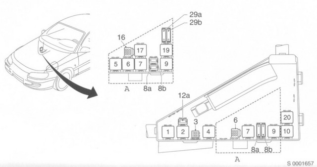
Note: The Omega cabin fuses are located below the steering wheel and are accessed by opening the drop down cover.

94-95 Cars
1--30A Window operation
2--15A Brake lamps, hazard warning flashers
3--30A Windscreen wipers, windscreen washer system
4--10A CD Changer
5--30A Electrically adjustable front seats
6--20A Radio
7--30A Electrically operated windows
8--10A Daylight running lamps (Scandinavia)
9--10A Automatic transmission (for the infirm)
10-
11-10A Heated exterior mirrors
12-20A Courtesy light, tunk lamp, hazard warning flashers, information display, radio
13-10A Electrically adjustable exterior mirrors
14-20A Power steering, cigarette lighter, heated front seats, electrically operated rear window blind
15-15A Reverse lamps, cigarette lighter, glove compartment lamp,automatic transmission, automatic level control system, cruise control, ventilation for rear door windows, position memory for seat and mirror adjustment
16-20A Fog lamps
17-20A Horn
18-20A Fuel pump (useful to remove then run engine to de-pressurise fuel system when changing fuel filter etc!)
19-10A ABS, TC
20-20A Heated rear seats, electrically operated rear window blind, central locking system
21-10A Main beam (left)
22-10A Dipped beam (left) headlamp range adjustment
23-10A Parking and tail lamps
24-20A
25-20A Sunroof
26-10A Number plate lamp, information display, headlamp washer system
27-20A Automatic level control system
28-10A Fog tail lamp
29-20A Terminal 30. constant current for caravan/trailer 30-10A Parking and tail lamps (right)
31-10A Dipped beam (right), headlamp range adjustment
32-10A Main beam (right), control indicators
33-30A Heater fan, air-conditioning system
34-40A Heated rear window

96-97 cars
1--30A Window operation
2--15A Brake lamps, hazard warning flashers
3--30A Windscreen wipers, windscreen washer system
4--10A CD Changer
5--30A Electrically adjustable front seats
6--10A Radio
7--30A Electrically operated windows
8--10A Daylight running lamps (Scandinavia)
9--10A Automatic transmission (for the infirm)
10-
11-10A Heated exterior mirrors
12-20A Courtesy light, tunk lamp, hazard warning flashers, information display, radio
13-10A Electrically adjustable exterior mirrors
14-20A Power steering, cigarette lighter, heated front seats, electrically operated rear window blind, air circulation system, electric air conditioning, anti-theft alarm system, heated rear seats
15-15A Reverse lamps, cigarette lighter, glove compartment lamp, automatic transmission, automatic level control system, cruise control, ventilation for rear door windows, seat and mirror adjustment, radio
16-20A Fog lamps
17-20A Horn (not the pot noodle variety)
18-20A Fuel pump (useful to remove then run engine to de-pressurise fuel system when changing fuel filter etc!)
19-10A ABS, TC
20-20A Heated rear seats, electrically operated rear window blind, central locking, courtesey lamp
21-10A Main beam (left)
22-10A Dipped beam (left) headlamp range adjustment
23-10A Parking and tail lamps
24-
25-20A Sunroof
26-10A Number plate lamp, information display, headlamp washer system
27-20A Automatic level control system
28-10A Fog tail lamp
29-20A Terminal 30. constant current for caravan/trailer (pikey optional fit, can be used for simple audio instals)
30-10A Parking and tail lamps (right)
31-10A Dipped beam (right), headlamp range adjustment
32-10A Main beam (right), control indicators
33-30A Heater fan, air-conditioning system, electric air-conditioning system (climate)
34-40A Heated rear window

98-2003 cars
1--30A Window operation
2--15A Brake lamps, hazard warning flashers
3--30A Windscreen wipers, windscreen washer system
4--15A Cooling fan
5--30A Electrically adjustable front seats
6--20A Radio
7--30A Electrically operated windows
8--10A Daylight running lamps (Scandinavia)
9--10A Automatic transmission (for the infirm)
10-30A Heated diesel fuel filter
11-10A Heated exterior mirrors
12-20A Courtesy light, tunk lamp, hazard warning flashers, information display, radio, navigation system
13-10A Electrically adjustable exterior mirrors
14-30A Power steering, cigarette lighter, heated front seats, electrically operated rear window blind, air circulation system, electric air conditioning, heated rear window
15-20A Reverse lamps, glove compartment lamp, automatic level control system, cruise control, seat and mirror adjustment, radio, heated rear seats, sun roof, instrument illumination, window operation, cooling fan, headlamp range adjustment
16-20A Fog lamps
17-20A Horn (not the pot noodle variety)
18-20A Fuel pump (useful to remove then run engine to de-pressurise fuel system when changing fuel filter etc!)
19-10A ABS, TC
20-20A Courtesy lamp, seat heating, central locking, rear window blind
21-10A Main beam (left)
22-10A Dipped beam (left) headlamp range adjustment
23-10A Parking and tail lamps
24-20A Coolant heating
25-20A Sunroof
26-10A Number plate lamp, information display, headlamp washer system
27-20A Automatic level control system, rear accessory socket
28-20A Fog tail lamp
29-30A Terminal 30. constant current for caravan/trailer (pikey optional fit, can be used for simple audio instals)
30-10A Parking and tail lamps (right)
31-15A Dipped beam (right), headlamp range adjustment
32-10A Main beam (right), control indicators
33-30A Heater fan, air-conditioning system, electric air-conditioning system (climate)
34-40A Heated rear window


118
Omega Common Issues and FAQ / Knock Sensor
« on: 06 September 2006, 17:41:44 »
All Omega Petrols engines utilise knock sensor(s) in the control of ignition timing.

Knock is very rarely heard on modern engines thanks mainly to the presence of knock sensors and knock control. Knock is more commonly known as 'pinking', a phenomenon many will know from the old distributor based ignition systems where the timing was to far advanced. Knock also occurs at different points depending on the quality of fuel used i.e. as a rule of thumb, the lower the Ron value of fuel the more retarded (closer to TDC) the ignition timing needs to be. Those who remember the introduction of unleaded fuel may remember how the timing had to be retarded by approx 5 deg to accommodate the lower RON value (if the valve seats could cope with it!).

The optimum point of combustion occurs just after the onset of 'knock' and it is important to ignite the fuel at this point to gain maximum power and maximum efficiency.

The knock sensor is little more than a microphone which is mounted onto the side of the engine block, the ECU advances the timing on every cycle until knock occurs (detected by the sensor) at which point it retards the timing (often by as little as 2 deg) before repeating the cycle. The detected timing values on some systems are used to update the timing Map and hence the ECU can adapt to engine wear etc. This method also allows the ECU to adapt to higher/lower octane fuels automatically.

Some later control systems with coil per plug set-ups also use the knock sensor to detect if the cylinder has fired which allows it record miss fires.

Points to note:

1) The sensor utilises a screened Coax cable to reduce the level of interference that can occur from the high voltage ignition systems and other high electrical noise engine systems. As such it is essential to try to maintain this screening if repairing damaged cables.

2) The knock sensor is a VERY reliable device and not one that I have ever known to truly fail. I have however seen them on V6 power plants where the cable has been trapped and damaged under the cam covers following gasket replacement (passenger side) or caught in the aux belt (drivers side).

3) On the V6 its worth noting that where there are more than one sensor (note also includes the lambda sensors) the numbering follows the cylinder numbering i.e. knock sensor number one is the drivers side on cylinder bank 1-3-5 etc.

4) Under failure conditions, the ECU enters a limp home mode where the timing is retarded to protect the cylinders. This results in the engine running and idling perfectly but, there is a BIG drop in output power.

5) A crude method for testing your DIS pack is to unplug the knock sensor and run the engine, the retarded timing will result in a higher voltage being required to ignite the fuel and hence a weak DIS pack will often miss fire. Note though, this can be terminal to a failing DIS pack!

119
Omega Common Issues and FAQ / Lambda Sensor
« on: 14 August 2006, 13:04:15 »
The lambda sensor is known by a number of different names i.e.

Oxygen sensor
Lambda sensor
Exhaust Gas Oxygen Sensor (EGO)
O2 Sensor

etc

This is a simple device which sits in the exhaust front pipe or manifold and monitors the exhaust gases for the presence of oxygen.


Its operation is fairly simple and its constructed from a plate of ceramic or metal with a platinum coating. Some alternative types are constructed using a Zirconium dioxide material.

The device produces a low voltage (between 0.2 and 1.4 V depending on the sensor type) which is related to the oxygen content. Reality is that the non-linearity of the voltage is such that the ECU can only really get a lean/rich indication from the sensor.

On lean burn engines a different type of sensor is required as the mixture is run deliberately weak when cruising, this requires the use of a wide band oxygen sensor. No Omega uses this method of control.

It is important to note the a lambda sensor only works when its hot and as such normally includes a heater to get it up to temperature quickly. The omega ones as a result appear as two types:

3 Wire - Used on the V6, One wire is the sensor output with the other sensor output being earthed via the sensor body to the exhaust. The two additional wires are the heater assembly.

4 Wire - Used on the 4 pots, two wires for the sensor and two for the heater.

The heater resistance is normally around the 4-10 ohm mark.

The ECU controls the mixture by monitoring the sensor reading, if the sensor is reporting the mixture as lean then it rich-ens the mixture by extending the fuel injector period (see other FAQ on fuel injectors), until the sensor flips to the rich indication, it then weakens the mixture until it again reports a lean mixture, this repeats continuously.

Later units have 2 or 4 lambda sensors, this helps to reduce pollutants further by monitoring the oxygen content before and after the cat and comparing the two values.

Thing to note:

1) Lambda sensors rarely fail but, they can be confused due to blocked or leaking exhausts. A leaking exhaust may well pop gas causing a ticking noise out as the pressure rises due to an exhaust stroke passing through it but, this pressure pulse is also followed by negative pressure after the exhaust valve has shut which draws air in.

2) The lambda sensor will not work until its VERY hot and hence the presence of a heater to speed up the heat-up period. If the heater is faulty then a heater coil fault may be flagged, in the case of the V6 the ECU cant monitor the heater directly and is probably actually reporting a slow switching time from the sensor (i.e. its a bit cooler then the optimum). As such you would need to measure the resistance of the heater coil to determine if it is really this at fault.

3) These can be sods to remove and replace, they really need soaking in a very good penetrating fluid.....often the threads are stripped from the sensor body on removal and the front pipe threads then need chasing out.

120
Omega Common Issues and FAQ / Mass Air Flow Sensor
« on: 09 August 2006, 13:22:52 »
The Mass Air Flow Sensor (MAF sensor) is key to the operation and mixture control of the engine system.

Because the combustion process is simply speaking a chemical reaction which is triggered by heat (in the form a of a spark) or compression (on a diesel) its essential to know how much air the engine is using in order to inject the correct amount of fuel and ensure that complete combustion occurs.

Air mass is measured in preference to air flow because the density of air (and hence the oxygen content) varies with humidity, altitude and temperature. Its the oxygen that we are using in the combustion process.

The MAF has evolved considerably over the years and started life as a moving vane/flap type arrangement (as used on older fuel injection systems i.e. the 24V straight six Carlton/Senator engine) which could only measure air flow to the hot film method which is used across all the Omegas engines (with the exception of the very early 2.5 diesel power plants). This gives the advantage of no moving parts, greater reliability and more accurate air measurement.

Note: add phott here.

The principle of operation is simple, a small hybrid circuit is placed into the the air flow. The membrane has a thin film temperature sensor printed on the upstream side, and one on the downstream side. A heater is integrated in the center of the membrane which maintains a constant temperature. the current through this varies as the film is heated and cooled by the air flow (the resistance of the film varies with temperature). Without any airflow, the temperature profile across the membrane is uniform i.e. both temp sensors see the same temperature. When air flows across the membrane, the upstream temp sensor cools differently than the downstream side (the upstream one will see the heat from the heater). The difference between the upstream and downstream temperature indicates the mass airflow.

Points to note:

1) It is not unusual for people to get MAF fault codes raised and there is not a fault with the sensor, the ECU will raise an error if the readings from the MAF are lower than what it is expects given the operating conditions of the engine.

i.e. the MAF might be reporting a typical idle air flow reading when the engine is doing 3000rpm, this may well be an air leak and un-metered air is entering the system.

or

At idle (not so relevant on Omega engines but, true of the new breed of power plants), the engine might be idling badly and a MAF code could be raised, reality is it could be that the EGR valve is stuck open.

Reality is with MAF faults that further live values should be viewed as part of the overall diagnostics.

2) The MAF sensor elements are very sensitive, you don't want any dirt getting into them. This can be helped by ensuring the air filter is always fitted and is changed at the correct service intervals. Also, cone filters tend to be of the clean and re-oil variety, this is not good as the oil can get sucked through and deposited on the MAF sensor.

3) The MAF sensor is easy to find, it is normaly located in between the airfilter housing and the throttle. In teh case of the V6 it is just below the first 90 deg bend as the pipe exits the air filter. The devcie it self is a tube of betwen 50 and 150mm in length (later ones are smaller i.e. on the 2.2)

Pages: 1 2 3 4 5 6 7 [8] 9 10 11 12 13 14 15 ... 29

Page created in 0.026 seconds with 14 queries.