Omega Owners Forum

Please login or register.

Login with username, password and session length
Advanced search  

News:

Please check the Forum Guidelines at the top of the Newbie section

Show Posts

This section allows you to view all posts made by this member. Note that you can only see posts made in areas you currently have access to.

Topics - Marks DTM Calib

Pages: 1 2 3 4 5 6 [7] 8 9 10 11 12 13 14 ... 29
91
Maintenance Guides / Diff Oil Change
« on: 22 October 2006, 13:42:16 »
The Omega utilises a 'sealed for life' rear differential unit mounted on the rear sub-frame assembly.

At high mileage it may be worth changing this oil and, if you have a limited slip diff, its worth changing it every 50K or so miles to ensure the lubricants viscosity properties are good in order to get optimum operation (when iffy the diff can be felt to slip and grab when cornering at low speeds).

This is not a difficult job and is actually a reasonably quick task.

First, you need to jack one of the rear corners and support it on axle stands to allow easier access to the diff.

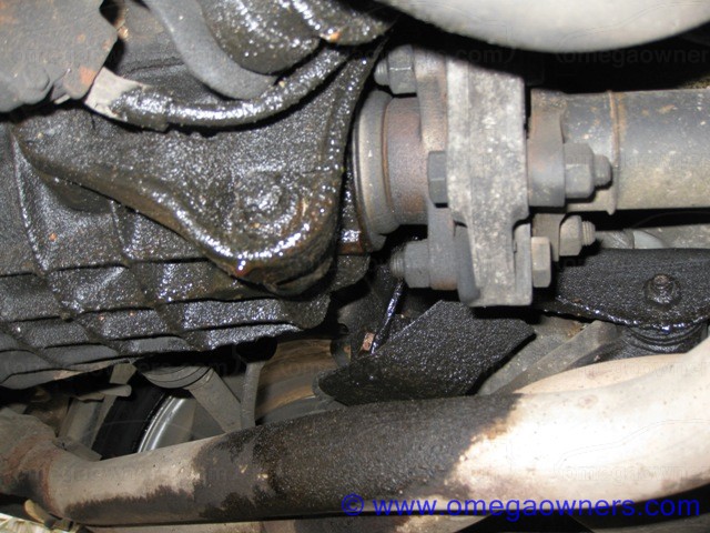
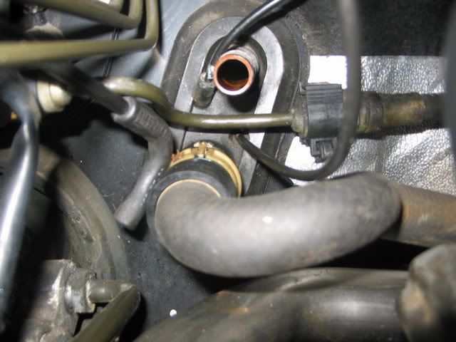
Once done, you need to disconnect the two ABS sensors from the connectors which are clipped into a set of holders on the floor pan above the diff (see photo below). If you remove them from the clips and ease them down there should be enough cable to allow you to easily free off the two small retaining clips with a small screwdriver and disconnect the connectors.

Now you need to slacken off the two rear diff support bolts (18mm) which can be seen either side of the ABS sensors in the attached pic, don't totally remove them just leave them slack in the housing so its still supporting the diff


Now undo the rear housing cover bolts (15mm 9 off) slacken off the bottom three a few turns first and then start at the top and work to the bottom, note, oil will start to leak out at this stage hence you need to catch it. Once the oil has drained away, support the rear off the diff on a jack or suitable support and remove the remaining plate and diff support bolts and remove the cover.

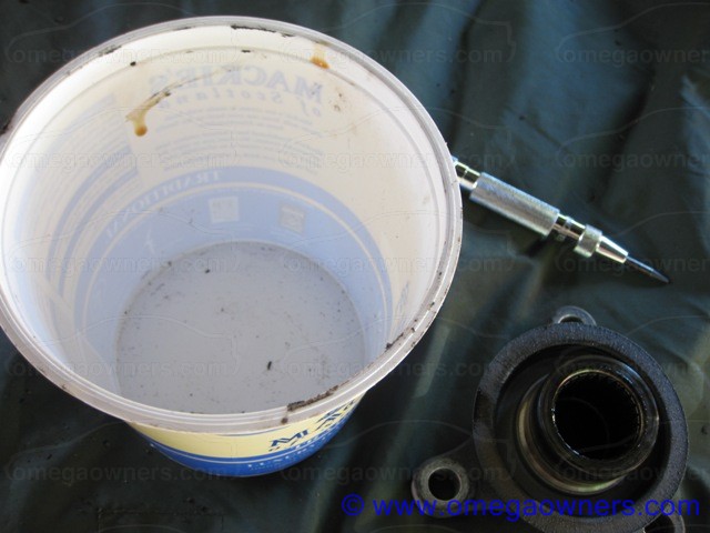
Its worth cleaning the cover and ABS sensors well whilst its off and ensure that the diff and plate mating surfaces are clean and oil free ready for assembly.

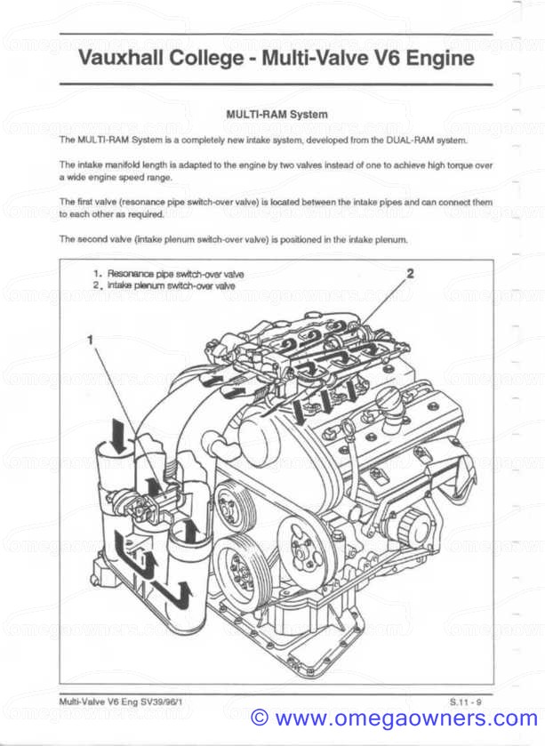
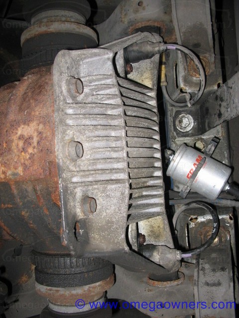
The following pic shows the internals, this is a shot of the one fitted to my ex plod estate and as you can see, its not an open frame setup due to it being a limited slip unit. The LSD assembly is the large section to the right of the crown wheel.


Once everything is clean, apply some suitable flange sealant (I use Loctite 598 which can be obtained from most places including Halfords) and refit the back plate tightening the bolts in a cross type formation (i.e. top, bottom, left right).

The bolts tightening torques are as follows:

Cover plate 15mm - 60Nm (apply thread-lock)
Diff support bolts 18mm - 90Nm

Once the sealant has had a short time to cure (the loctite above goes off in approx 15 minutes under pressure) the diff can be refilled, in the mean time, re-connect the ABS sensors and ref the connectors into the clips.

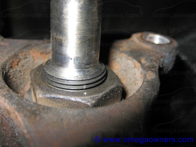
The level plug is mounted on the drivers side of the diff and is usually requires a T50 torx bit to remove it (may also be a 8mm allen key fitting). Fill via the level plug until oil starts to run out. The following oils are recommended:

Non LSD - Good quality SAE90 hypoid (approx 1litre required)
LSD - Good quality SAE90 hypoid with LSD additive (i.e. Silkolene BOA90LS available from Opie Oils approx 1.2 litres used)

Refit the level plug and tighten to a torque of 22Nm.

Remove the jack and axle stand and away you go!

Jobs a good one.

92
Maintenance Guides / Motronic 2.8.1 (V6 Engines) fault codes
« on: 06 October 2006, 17:33:34 »

10   Variant-Coding Not Programmed
13   O2 Sensor 1 Open Circuit
14   Coolant Temperature Voltage Low
15   Coolant Temperature Voltage High
16   Knock Signal Circuit 1
17   Knock Signal Circuit 2
18   Knock Control Module; Replace Electronic Control Unit (ECU)
19   Incorrect RPM Signal
21   Throttle Position Sensor (TPS) Voltage High
22   Throttle Position Sensor (TPS) Voltage Low
25   Injector Valve 1 Voltage High
26   Injector Valve 2 Voltage High
27   Injector Valve 3 Voltage High  
28   Injector Valve 4 Voltage High
29   Injector Valve 5 Voltage High
31   No Engine RPM Signal
32   Injector Valve 6 Voltage High
33   Exhaust Gas Recirculation (EGR) Valve Voltage Low
34   Exhaust Gas Recirculation (EGR) Valve Voltage High
38   O2 Sensor 1 Circuit Voltage Low
39   O2 Sensor 1 Circuit Voltage High
44   O2 Sensor 1 Lean Exhaust
45   O2 Sensor 1 Rich Exhaust
46   Secondary Air Pump Voltage Low
47   Secondary Air Pump Voltage High
48   Battery Voltage Low
49   Battery Voltage High
52   Telltale (Check Light) Voltage High
53   Fuel Pump Relay Voltage Low
54   Fuel Pump Relay Voltage High
55   Replace Electronic Control Unit (ECU)
56   Idle Air Control Voltage High
57   Idle Air Control Voltage Low
59   Intake Manifold Valve 1 Voltage Low
61   Fuel Tank Ventilation Valve Voltage Low
62   Fuel Tank Ventilation Valve Voltage High
63   Intake Manifold Valve 1 Voltage High
69   Intake Air Temperature Voltage Low
71   Intake Air Temperature Voltage High
73   Mass Air Flow Sensor Voltage Low
74   Mass Air Flow Sensor Voltage High
75   Torque Control Voltage Low
76   Continuous Torque Control
81   Injector Valve 1 Voltage Low
82   Injector Valve 2 Voltage Low
83   Injector Valve 3 Voltage Low
84   Injector Valve 4 Voltage Low
85   Injector Valve 5 Voltage Low
86   Injector Valve 6 Voltage Low
87   A/C Cutoff Relay Voltage Low
88   A/C Cutoff Relay Voltage High
89   O2 Sensor 2 Open Circuit
91   O2 Sensor 2 Circuit Voltage High
93   Hall Sensor Voltage Low
94   Hall Sensor Voltage High
98   O2 Sensor 2 Circuit Voltage Low
121   O2 Sensor 2 Lean Exhaust
122   O2 Sensor 2 Rich Exhaust
123   Intake Manifold Valve 1 Blocked
124   Intake Manifold Valve 2 Blocked
127   Camshaft Control Voltage Low
128   Camshaft Control Voltage High
129   Exhaust Gas Recirculation (EGR) Valve Feedback Voltage Low
131   Exhaust Gas Recirculation (EGR) Valve Feedback Voltage High
132   Exhaust Gas Recirculation (EGR) Valve Feedback Incorrect Signal
133   Intake Manifold Valve 2 Voltage Low
134   Intake Manifold Valve 2 Voltage High
135   Telltale (Checklight) Voltage Low
136   Unknown Output Driver Error
137   Electronic Control Unit (ECU) Box Temperature High
141   Secondary Air Pump Not Enough Air
142   Secondary Air Pump Air Without Pump
143   Immobiliser No Or Wrong Signal
144   Immobiliser No Signal
145   Immobiliser Wrong Signal

93
Maintenance Guides / Diff Pinion Oil Seal Change
« on: 08 September 2006, 14:33:21 »
The following is courtesy of Matchless with pictures supplied by seprim  :y

Tools required: 3 leg puller, 30mm deep socket, breaker bar or T bar plus extension pipe, centre punch, hammer, various spanners, suitable large socket / piece of tube / old bearing ring etc to drift new seal in and an 8mm allen key (or could be T50 torx) to check the diff oil level

Raise rear of car on ramps or jack up and support on stands. In either case chock both front wheels, front and back, and make sure the care is stable. You will be using considerable force so the car must be well supported.

This is often what you will be greeted with!


Mark the pinion drive flange and rubber coupling with spray paint etc to ensure you can put it back in the same place (optional but, good practice).


Un- bolt the propshaft rubber coupling from the pinion flange. Use a pry bar or large screwdriver to free the propshaft coupling from the pinion flange, note that the propshaft has an alignment spigot which engages with the pinion shaft so the propshaft has to be moved forwards about 1" / 25mm before it comes free.


Tie the propshaft out of the way.


Clean around the pinion nut and flange then use centre punch marks to mark the nut position, two dots on the nut and two on the flange. Do this carefully and very accurately, the nut sets the pre-load on the pinion shaft taper roller bearings, we cannot easily re-adjust the preload so must return the nut to its exact position.


Now undo the pinion nut, it will be very tight. You could bolt a length of angle to the pinion flange to help hold it still or get a helper to stand on the brake pedal.
Count the number of turns or flats needed to remove the nut, it is not essential but help with confidence when replacing the nut later.

Mark the relative position of the pinion shaft and flange, lightly centre punch the crest of one spine on the shaft and the adjacent valley on the flange.

A 3 leg puller is now needed to pull the flange off the pinion shaft. DO Not try hitting anything with a hammer, you will only ruin the diff bearings.

If you do not have a puller, you can re-fit the nut to the diff flange and use the prop section (without the rubber donut) and three of the nuts/bolts, to pull the flange off.


Almost off


Clean around the oil seal and rush off to get a bowl etc to catch the oil that is now dribbling out.


Hypoid oil stinks as you have now found out.
Note where the seal is positioned, flush with the diff case or slightly recessed.

Use a large screwdriver to lever the old seal out. Take care not to damage the shaft or casing in the process.

Insert the new seal. Easier said than done as the seal has an external lip which fits into a recess on the back of the flange, presumably to protect the main oil seal lip from dust & grot. I found an old piece of steam pipe which was the perfect diameter to drift the seal in, an suitable BIG socket, old wheel bearing ring etc would do.
If you cant find anything of the right diameter then a piece of hardwood can be used if very careful or the old seal!.


Start by trying the engage the seal by hand then use the hardwood as a protector and gently tap the seal home, tapping opposite sides at first, trying not to let the seal tip over. Once engaged in the bore, work around the seal tapping it in little by little until fully in place.

Clean the seal lips then wipe a little diff oil over the lips and the surface of the flange. Align your punch marks and replace the drive flange, it will only go on a little way then you have to re-fit the nut to continue pulling it into place. DO NOT try hitting it.

There will seem to be loads of play in the pinions shaft, don't panic, this will disappear as the flange is pressed home. Keep looking for you punch marks as you tighten the nut and finally align the marks exactly. (this is when it helps to have counted the number of turns and flats needed to remove the nut). Note, it will be bloody tight!

Replace the propshaft and tighten the bolts to the correct torque. If you have any doubts about the self-locking nuts then get new ones or use Locktite.

Check the oil level in the diff and top-up, note that limited slip diffs need a special oil.

Return car to ground and job done. All that remains is to put overalls in washing machine and discover that the smell of Hypoid oil will not wash out....of your overalls or the washer!!

Diff Pinion Seal - 24435952

94
Maintenance Guides / V6 Torque Values
« on: 23 August 2006, 21:32:01 »
DescriptionNmNotes
Adapter, fuel distributor pipe to intake bridge8
Adapter, fuel distributor pipe to fuel distributor pipe15
Starter to cylinder block40
Intake bridge to intake flange20
Intake flange to cylinder head20
Drive disc/flywheel to crankshaft65 + 30° + 15°     1,2
Exhaust manifold to cylinder head203
Oil filter housing cover to oil filter housing25
Heat exchanger cover to heat exchanger30
Heat exchanger cover to cylinder block20
DIS ignition module to member8
Torsional vibration damper to toothed belt drive gear20
Throttle body to intake plenum8
Pressure line to power steering pump28
Accelerator pedal module to bulkhead20
Link rod to stabiliser653
Alternator to cylinder block and oil pump35
Transmission to cylinder block (M8)20
Transmission to cylinder block (M12)60
Transmission holder to underbody454
Threaded sleeves to crankshaft bearing bridge8
Base plate, toothed belt tension roller and toothed belt guide roller to cylinder head40
Auxiliary aggregate(s) support to cylinder block35
Idler bracket to body55 + 75° + 15°1
Rear toothed belt cover to cylinder head and oil pump (M6)8
Rear toothed belt cover to cylinder head and oil pump (M8)10
Crankshaft pulse pick-up in cylinder block8
Crankshaft pulse pick-up disc to crankshaft151
Refrigerant lines to compressor40
Ribbed V-belt pulley to coolant pump8 + 30° + 30° 1 or 12Nm+loctite
Ribbed V-belt pulley to power steering pump20 + 30° + 15°3 or 20Nm+loctite
Ribbed v-belt tension roller to cylinder head35
Knock sensor to cylinder block20
Fuel lines to adapter, fuel distributor pipe15
Fuel distributor pipe to intake bridge8
Coolant bridge to cylinder head305
Coolant intake pipe to exhaust manifold8
Coolant intake pipe to cylinder block20
Coolant pump to cylinder block25
Coolant pipe and engine transport shackle to cylinder head25
Ball joint to steering knuckle1003
Crankshaft bearing bridge to cylinder block20
Crankshaft bearing cap and crankshaft bearing bridge to cylinder block50 + 60° + 15°1
Oxygen sensor in front exhaust pipe306
Steering arm to steering shaft1603
Solenoid valve for intake plenum switchover valve to switchover valve8
Secondary air metal pipe to exhaust manifold20
Engine damping block to engine bracket40
Engine vent housing to cylinder block8
Engine damping block to front axle body55
Engine bracket to cylinder block40
Engine bracket, engine damping block to cylinder block60
Camshaft bearing caps to cylinder head8
Camshaft sprocket to camshaft50 + 60° + 15°1
Camshaft sensor to camshaft bearing cap8

95
Maintenance Guides / Removing An Omega headlight
« on: 07 August 2006, 17:09:20 »
Created by markjay


96
Maintenance Guides / V6 Multiram operation
« on: 25 July 2006, 16:09:36 »
Following numerous questions about multiram, I have taken the decision to load the V6 Vaux college files on for all to see:


The multiram does a VERY good job of flattening out the torque curve and hence aiding economy.  
 
You need to consider that for optimum torque you need high air speed in the inlet........so if the inlet is small and long you get high inlet airspeed at low revs but a restriction at high revs (good bottom end torque but nothing higher in the rev range), if its short and large you get low inlet air speed at low revs and good inlet air speed at high revs (no bottom end torque)......the multiram allows a good compromise on both i.e. high air speed at low revs and high air speed with low restriction at high revs.....its a dam good system.

97
Maintenance Guides / Repairing the Alternator
« on: 24 July 2006, 21:29:04 »
The alternators fail in two basic ways.

Low output (no charge) and high output (high volts)

The Omega alternator, once removed, is easy to work on. Simply remove the the three cover securing screws on the rear.


This will reveal the diode pack (which VERY rarely fails on these models, large black metal assembly at the rear of the photo) and the brush/regulator pack (combined part, at front of photo, the regulator is the black item).


The two main casues of failure are a failed regualator (nomaly fails short and causes high output voltage) and low output. If the output is high then obtain a replacement brush/regulator pack and fit it. This is easily done by simply removing the two securing screws visable in the above picture.

If the ouput is low then try this first;

The connection from the brush/regultor module to 0V is via the securing screws, the positive supply is via a spring contact which can be seen here:


This picture clearly shows the problem, corrosion has set in and caused the contact to become poor, simply clean this up and refit, idealy this connection should be soldered to prevent future re-occurance.

Re-assemble an refit......and hopefuly an easy and very cheap fix!

Note: This some times shows early signs of failure by a slight flashing of the dash/MID lighting......

As an addition, the alternators used are easy to work on and noisey bearings are reasonably easy to replace using standard off the shelf parts.

The bearing sizes are as follows:

Front Bearing - 6303 2RS      ID=17mm OD=47mm D=14mm
Rear Bearing - 6203 2RS      ID=17mm OD=40mm D=12mm

98
Maintenance Guides / How to check the auto box fluid level
« on: 13 July 2006, 10:39:46 »
This is the method which I use and find it works quite well. (note pic, to follow).

First, the gearbox oil needs to be warm, idealy between about 40-80 deg's so take the car for a short run.

Now jack up the drivers side (passenger side if left hand drive) and support on a suitable axle stand. Note, the car needs to be on a fairly flat surface.

Warning: The Catalytic converters get very hot and the level plug is very close to them so be careful!)

Place a suitable container underneath the auto box and locate the oil level plug, slacken it off with a 13mm socket (you could use a spanner but, a socket is easier), dont fully remove it.

Now chock the wheels, ensure the auto box is in park and start the engine.

Carefuly reach under the car, position the container below the level plug and remove the level plug.

Using Dextron 3 ATF top the fluid level up until it just starts to run out, for top ups I buy a 1 litre bottle with the long extandable plastic delivery tube, insert the tube into the level plug and squeeze.

Now, with the engine still running, lower the car off the jack, the excess fluid will run out and into the container.

Jack the car again and refit the level plug with a new washer (if you dont have one then heat it up to re-anneal the old washer before fitting).

Wipe off any oil runs from the gearbox sump and jobs a good un

99
Maintenance Guides / Removing the instrument panel
« on: 11 July 2006, 12:54:36 »
Remove the two centre air vents (I use a couple of butter knives) by levering gently on either end of them to pop them out, some times made easier by pointing the vents fully down.

Remove the two screws exposed once the vents are removed and extract the vent assembly.

Remove the screw securing the left had end of the instrument panel.

Tilt the steering wheel fully down (on non adjustable columns you need to remove the upper steering wheel cowl by removing the screws which can be accessed with the steering wheel in the 9 Oclock and then 3 Oclock positions) and then remove the screw securing the bottom of the instrument panel.

Grasp the left had end of the panel and pull forward, then reach in behind to release the MID/TID/GID/CID connector(s) (the grey type connector has a cam locking system which needs to be release and rotated through 90 degress, the yellow type connector has a black plastic lock which needs to be slid outwards).

The panel then simply pops out.

100
Remove the front door cards as per the other maintenance guides

Carefully remove the internal plastic door skin to gain access to the lock mechanism, dont damage it as the side air bags on later cars rely on theis being a good seal.

Unclip lock mechanism connecting rods by unclipping the scuring clips and rotating to allo the rods to become free, there is

- one at the front
- one at the back of the mechanism.

Undo the three large torx screws around the striker plate on the ned of the door
Disconnect the multiplug from the base of the solenoid & remove the mechanism and solenoid by lowering to release outer door latch linkage and then lifting out.

Replace solenoid by removing 2 screws and unhooking.

Re-fit by reversing the above - take care to ensure that the arm from the exterior door handle is located correctly in the top of the mechanism (it just sits freely in a plastic ring - no connectors). Of course, test lock before re-fitting door card!  

Solenoid Part Numbers: Pre mini-facelift: 90449074
Post mini-facelift: 90493702

Price approx. £35-£40 + VAT from Vauxhall

Beware that the two motor assemblies have different connectors so are not easliy interchangeable


101
Maintenance Guides / 2.0 and 2.2 Cam cover gasket replacement
« on: 10 July 2006, 22:04:32 »
For the 2.2 engines (Z22XE), first remove the ignition module, for 2.0 (X20XEV) remove the spark plug lead cover.

Remove the three crankcase ventilation hoses from the rocker cover (two on throttle/inlet side and one on the exhaust side).
Disconnect the camshaft sensor plug and place lead out of the way.

Remove the spark plug leads (2.0 only), this is an opportune moment to test the leads with a DVM, they should read between 2Kohm and 10Kohm, also inspect the leads for damage and replace if neccasary.

Remove the rocker cover, its worth giving it a good clean with degreaser (parafin or diesel also works well) and also check the breather ports to make sure they are nice and clear. Remove and discard the main rocker seal and the sealing rings around the bolt holes.

Clean the head surface well and ensure its dry, I wipe it down with thinners to remove any grease or oil, any good solvent will do (i.e. the wifes nail varnish remover )
Apply the sealing compound to the areas to the side of the cam clamps which are at the pulley end of the cams (i.e. the front of the engine on the Omega). It should be applied so as its parralel with the cams and starts at the front of the head and finishes at the rear of the cam clamp. Ensure that it is a reasonable size bead which is touching the cam clamps.

Refit the cylinder head cover with the new sealing rings fitted and the new main gasket to a torque of only 8 Nm / 6 lbf. ft. Overtighten it and you will distort the cover causing it to leak again.

Refit the spark plug leads on the 2.0

Reattach the cam sensor connector and on the 2.0 re-fit the spark plug cover (note only 3Nm for these securing bolts!) and on the 2.2 refit the ignition module.

Re-attach the 3 camcover vent hoses, its worth checking they are nice and clean and not full of crudd, its also a good time to clean the throttle body and idle valve out!

102
Maintenance Guides / Reducing wind noise
« on: 10 July 2006, 22:03:47 »
nice little 15 minute job for you all.

Given that some of the cars on here are higher mileage and may not have fully original body panels this is one little job that can help with the following:

1. Wind noise.
2. Door closure.

Check the door alignment by looking down the line of the car, feel the gap on the door jams with your finger. If any of the doors sit slightly proud around the catch area then adjust the catch plate in the following manner:

1. Take an appropriately sized Torx bit and slightly slacken the catch plate bolts on the B pillar (or C pillar if adjusting the rear doors) and gently tap in the direction of adjustment required.

2. Re-tighten the catch plate bolts and re-try closing the door.

3. Repeat until door is a good fit.

Nice easy one which can yield excellent results and not to bad to do with the cold weather upon us!

This works on pretty much all Vauxhalls (later models, eg Astra G's have alignment marks in the metal) so give it a go.....

103
Maintenance Guides / V6 camshaft identification
« on: 10 July 2006, 22:01:59 »
Attached is an extract from the Vauxhall college V6 manual which gives information on how to identify the different camshafts fitted to the Ecotec power plants.

Note, although it refers to coloured markings, often these are not visible so look for stamps in the camshaft castings near the pulley end.


A very effective performance mod on the 2.5 V6 is to fit the 3.0 inlet and exhaust cams, this gives about 18bhp more!

104
Maintenance Guides / V6 engine bay vaccum pipes
« on: 10 July 2006, 22:00:04 »
I get a lot of questions about the arrangement of the vac pipes in the Omega engine bay on the V6 models.

The V6 uses Vacuum for a number of things

Multiram
Air injection
Brake servo
Climate/heater control.

It is important that these pipes are connected correctly and have no leaks to get the best performance/economy from your engine and to guarantee operation of the heating/climate systems. Unfortunately they are often re-fitted incorrectly by garages following work and in some cases some of the pipes may have been in-correctly routed resulting in chafing and the pipes wearing through.

As an example, I know of a 3.0MV6 Omega which when put on the rolling road was producing around 170Bhp, correct fitment of the multiram pipe work restore this to the full 200Bhp plus!


Later setup, identifiable by the presence of a vac tank on the base of the inlet trumpets at the front of the engine bay


Earlier setup, similar to above but, no separate vac tank for the multiram, instead it is T'ed off the heater vacuum line where it passes through the bulk head.


As an additional note, the following picture shows where the vac pipes pass through the bulk head to the climate/heater controls in the cabin and return to the heater bypass valve.


The connection on the left is the vac feed to the cabin controls and the one on the right is the return which connects to the bypass valve.

I have seen many of these setups where this T-piece has been moved to the brake servo which is great but, at full throttle there is very little vacuum so the multiram stops working

Note also that the vac pipes must be connected correctly to the solenoid valves with the VAC feed connected to the nose connection and the output (to the actuator) on the side connection.

For those with a 4 pot, the setup is very similar with the exclusion of the mulktirams (and air injection on the 2.2)

105
Omega Common Issues and FAQ / Omega Tyre Pressures
« on: 14 April 2007, 21:42:56 »

Pages: 1 2 3 4 5 6 [7] 8 9 10 11 12 13 14 ... 29

Page created in 0.03 seconds with 14 queries.