Omega Owners Forum

Please login or register.

Login with username, password and session length
Advanced search  

News:

Please check the Forum Guidelines at the top of the Newbie section

Show Posts

This section allows you to view all posts made by this member. Note that you can only see posts made in areas you currently have access to.

Topics - Marks DTM Calib

Pages: 1 2 3 4 5 [6] 7 8 9 10 11 12 13 ... 29
76
General Car Chat / Finaly fitted the engine!
« on: 10 October 2011, 08:29:35 »
Yesterday I finaly got around to fitting the engine on the little Dexta tractor:


Now I can bolt a few more bits back on which are ready to fit!

77
Maintenance Guides / Replacing the bonnet latch spring
« on: 12 April 2011, 21:22:13 »
If you are having issues opening the bonnet and have already tried adjusting the cable then read on.

The latch spring on the bonnet can wear with use and has also been seen to become distorted if forced.

This is a nice easy and cheap part to replace.

So, start by removing the end caps on the radiator cover and extract the two screws that secure the cover in place. Remove the cover.


If its a pre-facelift car, remove the front grill.

Now slacken the bonnet release cable by slackening the securing bolt.


Remove the bolt which holds the bonnet cable cover in place.


Using a set of pliers, unclip the bonnet latch spring from the slam panel.


Reach up under the slam panel to work the bonnet cable from the end of the latch spring.


Extract the latch spring through the slam panel hole.


Re-fit is the reverse of removal, apply grease to the spring assembly and tighten the cable as per the cable adjustment guide.

All done!

Spring part number: 90494843
Replacement cable grip if required 11070693

78
Maintenance Guides / Cleaning the V6 crankcase breather setup
« on: 27 September 2010, 11:39:26 »
As with any engine, the key to reliability is effective servicing.

When combustion occurs, blow by gases (the fumes which pass by the piston rings), accumulate within the engine casing.

In years gone by, these fumes would have been vented to atmosphere (if you were lucky there may have been a catch tank) but, emission rules mean that this is no longer an option.

As a result, engine manufacturers 'capture' these gases and feed them into the inlet to be burnt and expelled via the exhaust. This is all carried out by the engine breather setup.

In addition to the blow by gases, some oil vapour also passes through these breathers and this is a key contributor to the 'blocking' issue. This is made worse if the oil is old and 'past its best' as it takes on a tar like constituency.

So, onto the cleaning

To start, its recommended that you have the following items:
  • Carb cleaner (or similar suitable cleaner)
  • Breather bridge to plenum seal 1 off required - 90467543
  • Breather bridge to throttle O ring 2 off required (4 off on extended plenum's) - 90500983
All of the above is cheap.

Remove the plenum as detailed in:
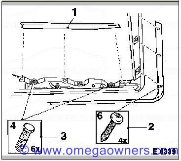
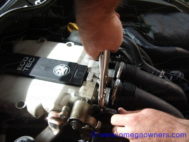
V6 Plenum Removal

Using a flat blade screwdriver, ease the ecotec cover off so as to expose the torx retaining screw for the breather bridge assembly.


Remove the 4 TORX bolts and separate the throttle body from the plenum. Now remove the torx bolt holding the breather bridge to the plenum and lift it off. On later units with the extended plenum assembly, an additional short breather section is fitted, this should be removed and cleaned in the same way as the main breather bridge.


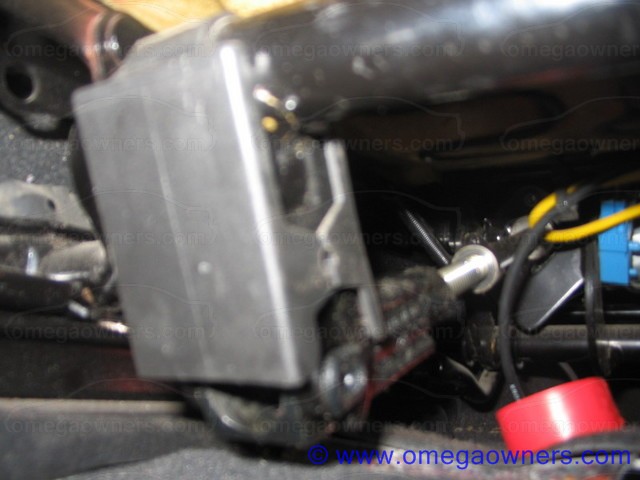
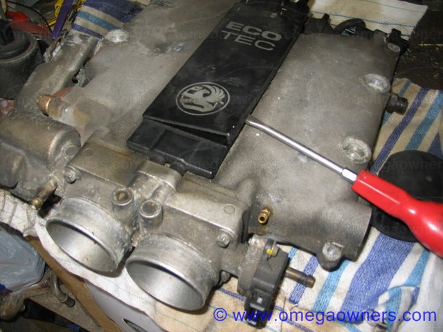
The next pic shows the three parts removed, the throttles at the front, the breather bridge to the left and the plenum in the center.


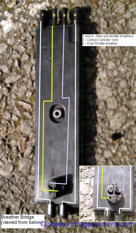
The black breather bridge needs a good shot of Carb cleaner and pay particular attention to the underside where there should be 4 smallish holes visible.


Spend plenty of time cleaning the throttle assembly, paint stripper is excellent for removing the tough carbon off the rear of the butterflies as is Carb cleaner, pay close attention to the edges of the throttle butterflies.

This is also a good time to check the throttle butterflies, they should close pretty much fully shut (within machining tolerances anyway) but, don't over do it as they can stick shut.

Its not unknown for some mechanics to wind the throttle stop in to overcome stalling issues. This is a BAD idea as it means the idle is no longer under ECU control and the ECU can not effectively compensate for varying idle demands from air con, steering input and alternator loads.

So check the setting is adjusted so that the throttles are shut but they don't stick (if you wind out the throttle stop until you can just feel it stick, then wind it back in half a turn is about right!)

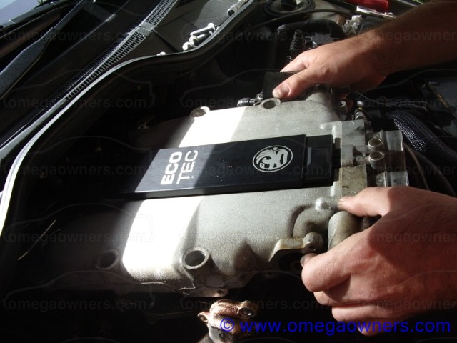
When these items are clean, fit the new seals to the breather bridge, re-assemble the plenum system ready to re-fit to the car as shown. Its worth putting a thin wipe of grease on the seals of the breather bridge to aid assembly.


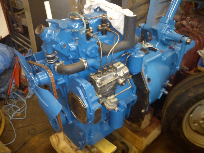
And yes, that is the same plenum as in the first picture!

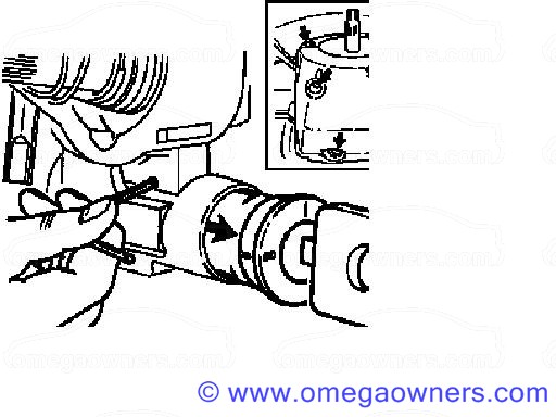
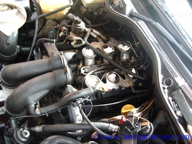
Remove the 2 breather tubes - 1 small one from the breather box, 1 large one that divides into two from the same breather box.

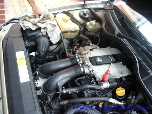
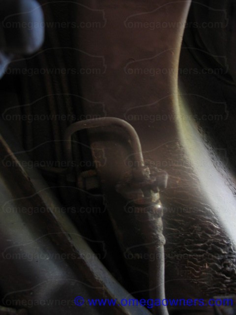
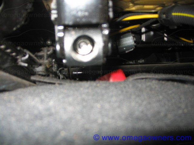
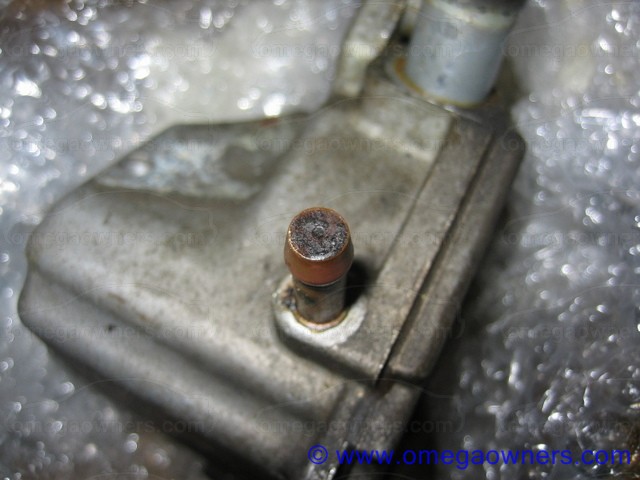
Next we need to clean the vent housing, this is mounted at the rear of the 1-3-5 head (driver's side in the UK) and has two connections located on the top face, one small and one large.

The smaller pipe (brass) has a very small hole in the center, this can be cleared with ideally a small drill (approx 1.6mm) or a suitable piece of wire.


Its also worth cleaning the area around the breather holes for completeness (and it makes it look nice!)
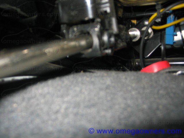
Next, the big pipe.


Again, a drill bit is recommended as this ensures that crud is removed (twist the drill as you go) rather than pushed into the breather box.

Do beware of squirting loads of Carb cleaner into the breather holes as this will have an adverse effect on the oil.

79
Maintenance Guides / Removing the sunroof glass panel
« on: 26 January 2009, 19:57:16 »
To remove the sunroof glass panel do as follows;


Slide the sun cover backwards and open the sunroof slightly (backwards, not tilt).

Unscrew the trim panel (Item 2, 4 screws) and remove the trim panel

Close the sunroof.

Unclip the side trim pieces (Item 1).

Remove the 6 bolts.

The sunroof glass will now lift out.

Remove cover.

80
Maintenance Guides / Y26SE and Y32SE Motronic ME3.11 Fault Codes
« on: 05 September 2008, 14:01:34 »
Below are the codes for the Y26SE and Y32SE ECU's (Motronic ME3.11) as used on the 3.2 and 2.6 V6 petrol engines.

Note, many have the codes have multiple causes the details of which will only be displayed on a quality scan tool.

P0100 Mass or volume air flow circuit high input
P0100 Mass or volume air flow circuit low input
P0100 Mass or volume air flow circuit range/performanceProblem
P0110 Intake Air Temperature Circuit High Input
P0110 Intake Air Temperature Circuit Low Input
P0115 Engine Coolant Temperature Circuit High Input
P0115 Engine Coolant Temperature Circuit Low Input
P0115 Engine coolant temperature circuit range/performanceProblem
P0120 Throttle/PedalPosition Incorrect Ratio
P0120 Throttle/pedalPosition sensor/switch "A" circuit high input
P0120 Throttle/pedalPosition sensor/switch "A" circuit low input
P0120 Throttle/pedalPosition sensor/switch "A" circuit range/performanceProblem
P0130 O2 Sensor Circuit High Voltage (Bank 1 Sensor 1)
P0130 O2 Sensor Circuit Slow Response (Bank 1 Sensor 1)
P0130 O2 Sensor Circuit No Activity Detected (Bank 1 Sensor 1)
P0130 O2 sensor circuit malfunction (Bank 1 Sensor 1)
P0135 O2 Sensor Heater Circuit High Voltage (Bank 1 Sensor 1)
P0135 O2 Sensor Heater Circuit Low Voltage (Bank 1 Sensor 1)
P0135 O2 Sensor Heater Circuit Open (Bank 1 Sensor 1)
P0135 O2 sensor heater circuit malfunction (Bank 1 Sensor 1)
P0136 O2 Sensor Circuit High Voltage (Bank 1 Sensor 2)
P0136 O2 sensor circuit slow response (Bank 1 Sensor 2)
P0136 O2 Sensor Circuit No Activity Detected (Bank 1 Sensor 2)
P0136 O2 sensor circuit malfunction (Bank 1 Sensor 2)
P0141 O2 Sensor Heater Circuit High Voltage (Bank 1 Sensor 2)
P0141 O2 Sensor Heater Circuit Low Voltage (Bank 1 Sensor 2)
P0141 O2 Sensor Heater Circuit Open (Bank 1 Sensor 2)
P0141 O2 sensor heater circuit malfunction (Bank 1 Sensor 2)
P0150 O2 Sensor Circuit High Voltage (Bank 2 Sensor 1)
P0150 O2 Sensor Circuit Slow Response (Bank 2 Sensor 1)
P0150 O2 Sensor Circuit No Activity Detected (Bank 2 Sensor 1)
P0150 O2 sensor circuit malfunction (Bank 2 Sensor 1)
P0155 O2 Sensor Heater Circuit High Voltage (Bank 2 Sensor 1)
P0155 O2 Sensor Heater Circuit Low Voltage (Bank 2 Sensor 1)
P0155 O2 Sensor Heater Circuit Open (Bank 2 Sensor 1)
P0155 O2 sensor heater circuit malfunction (Bank 2 Sensor 1)
P0156 O2 sensor circuit malfunction (Bank 2 Sensor 2)
P0156 O2 sensor circuit slow response (Bank 2 Sensor 2)
P0156 O2 Sensor Circuit No Activity Detected (Bank 2 Sensor 2)
P0156 O2 sensor circuit malfunction (Bank 2 Sensor 2)
P0161 O2 Sensor Heater Circuit High Voltage (Bank 2 Sensor 2)
P0161 O2 Sensor Heater Circuit low Voltage (Bank 2 Sensor 2)
P0161 O2 Sensor Heater Circuit Open (Bank 2 Sensor 2)
P0161 O2 sensor heater circuit malfunction (Bank 2 Sensor 2)
P0170 Fuel trim malfunction (Bank 1)
P0173 Fuel trim malfunction (Bank 2)
P0201 Cylinder 1 injector circuit high
P0201 Cylinder 1 injector circuit low
P0201 Cylinder 1 Injector Circuit Open
P0202 Cylinder 2 injector circuit high
P0202 Cylinder 2 injector circuit low
P0202 Cylinder 2 Injector Circuit Open
P0203 Cylinder 3 injector circuit high
P0203 Cylinder 3 injector circuit low
P0203 Cylinder 3 Injector Circuit Open
P0204 Cylinder 4 injector circuit high
P0204 Cylinder 4 injector circuit low
P0204 Cylinder 4 Injector Circuit Open
P0205 Cylinder 5 injector circuit high
P0205 Cylinder 5 injector circuit low
P0205 Cylinder 5 Injector Circuit Open
P0206 Cylinder 6 injector circuit high
P0206 Cylinder 6 injector circuit low
P0206 Cylinder 6 Injector Circuit Open
P0219 Engine overspeed condition
P0220 Throttle/pedalPosition sensor/switch "B" circuit high input
P0220 Throttle/pedalPosition sensor/switch "B" circuit low input
P0220 Throttle/pedalPosition sensor/switch "B" circuit range/performanceProblem
P0230 FuelPumpPrimary Circuit High
P0230 FuelPumpPrimary Circuit Low
P0230 FuelPumpPrimary Circuit Open
P0300 Random/multiple cylinder misfire detected
P0301 Cylinder 1 Misfire Detected
P0302 Cylinder 2 Misfire Detected
P0303 Cylinder 3 Misfire Detected
P0304 Cylinder 4 Misfire Detected
P0305 Cylinder 5 Misfire Detected
P0306 Cylinder 6 Misfire Detected
P0325 Knock sensor 1 circuit high input (Bank 1 or single sensor)
P0325 Knock sensor 1 circuit low input (Bank 1 or single sensor)
P0330 Knock sensor 2 circuit high input (Bank 2)
P0330 Knock sensor 2 circuit low input (Bank 2)
P0335 CrankshaftPosition sensor "A" circuit malfunction
P0340 CamshaftPosition sensor circuit high input
P0340 CamshaftPosition Sensor Signal Missing
P0340 CamshaftPosition Sensor Circuit Range/Performance
P0340 CamshaftPosition sensor circuit low input
P0420 Catalyst System Efficiency Below Threshold (Bank 1)
P0430 Catalyst System Efficiency Below Threshold (Bank 2)
P0443 Evaporative emission control systemPurge control valve circuit shorted
P0443 Evaporative emission control systemPurge control valve circuit open
P0443 Evaporative emission control system gross leak detected
P0460 Fuel Level Sensor Circuit High Input Instrument
P0460 Fuel Level Sensor Circuit Low Input Instrument
P0500 Vehicle speed sensor malfunctionB-009
P0505 Idle control system RPM higher than expected
P0505 Idle control system RPM lower than expected
P0560 System Voltage High Input
P0560 System Voltage Low Input
P0560 System voltage malfunction
P0571 Cruise control/brake switch "A" circuit malfunction
P0602 Control ModuleProgramming Error
P0602 Control ModuleProgram Version Error
P0602 Vehicle Identification Number NotProgrammed
P0602 Variant-Coding NotProgrammed
P0607 Knock Sensor Circuit

81
Maintenance Guides / Removing the ignition lock assembly
« on: 13 June 2008, 11:42:17 »
Remove the upper and lower steering wheel cowls.

The upper cowl is secured by two screws on the front of the assembly which can be accessed by rotating the steering wheel to the 3.00 and then the 9.00 positions

The lower cowl is attached by 3 screws from below.

Now, insert the key and rotate it until it is in the I position.

Now insert a small allen key as shown below into the small hole in the steering lock assembly and remove the lock barrel.


When re-fitting, if the steering lock bolt snaps in (steering lock will be on) push locking stone downwards using a screwdriver until the retaining bolt snaps in

Now re-fit the lock assembly


Note: The following requires care!

With the lock assembly removed, it is now possible with great care (keep the key in the lock assembly) to dissassemble the lock mechanism (beware of small springs!) to remove, clean and then lube the 10 or so plungers.

It is also possible to adjust the plunger profiles using a fine file with the key fitted to overcome sticking ignition locks.

82
Maintenance Guides / Simtec 56.0/56.1 2.0l 16V Fault Codes
« on: 07 April 2008, 11:51:13 »
12 Initiation of diagnosis. n/a
13 Oxygen sensor Open circuit
14 Coolant temperature sensor Voltage low
15 Coolant temperature sensor Voltage high
16 Knock sensor signal circuit No change in voltage
19 Incorrect Revs per Minute (RPM) signal (crankshaft sensor) Incorrect signal, check sensor
21 Throttle position sensor (TPS) Voltage high
22 Throttle position sensor (TPS) Voltage low
23 Knock control module signal Out of range
24 Vehicle speed signal (VSS) No signal
25 Injector valve 1 Voltage high
26 Injector valve 2 Voltage high
27 Injector valve 3 Voltage high
28 Injector valve 4 Voltage high
37 Check light (fault code lamp) Voltage low
38 Oxygen sensor circuit Voltage high
39 Oxygen sensor circuit Voltage low
44 Oxygen sensor Lean exhaust (weak mixture)
45 Oxygen sensor Rich exhaust (rich mixture)
48 Battery Voltage low
49 Battery Voltage high
52 Check light (fault code lamp) Voltage high
53 Fuel pump relay Voltage low
54 Fuel pump relay Voltage high
55 Engine Control Unit (ECU) faulty Check chassis earth and ECU connector.
56 Idle air control Voltage high
57 Idle air control Voltage low
61 Fuel tank vent valve Voltage low
62 Fuel tank vent valve Voltage high
69 Intake air temperature sensor Voltage low
71 Intake air temperature sensor Voltage high
73 Mass air flow temperature Voltage low
74 Mass air flow temperature Voltage high
75 Torque control (automatic) Voltage low
76 Torque control (automatic) Continuous signal, ignition retard long
81 Injector valve 1 Voltage low. Injector short circuit to ground.
82 Injector valve 2 Voltage low. Injector short circuit to ground.
83 Injector valve 3 Voltage low. Injector short circuit to ground.
84 Injector valve 4 Voltage low. Injector short circuit to ground.
87 Air Conditioning (A/C) cut-off relay Voltage low
88 Air Conditioning (A/C) cut-off relay Voltage high  
91 Oxygen sensor heater Voltage high
92 Camshaft sensor Incorrect signal
98 Oxygen sensor heater Voltage low, open circuit

83
Maintenance Guides / Servicing the rear disc and parking brakes
« on: 10 July 2006, 21:52:30 »
First of all you need to chock the front wheels and release the handbrake, slacken the wheel nuts and jack the car in a safe manner (you need to get under it!), an axle stand should also be used for added safety.

Now remove the road wheel and place this under the sill (added safety plus its out the way).

Get under the car and remove the heat shields which cover the hand brake adjuster, its worth spraying these with penetrating fluid before starting this job as they can often be corroded. This can be done without removing the exhaust.

The heat shields are secured by 9 10mm nuts.

Now slacken the handbrake cable off with a 13mm deep socket (again this may need spraying with penetrating fluid to aid removal)


Next to the rear disc. Remove the securing bolt (normally a hex type drive)


Now, using a suitable drift, drive the pad securing pins out (in this case a large round bright nail is ideal!)


And remove the pads.


Then remove the two caliper securing bolts (19mm)


Support the caliper away from the work area and remove the disc. Sometimes it is necessary to back the hand brake shoes off. Do this by rotating the disc assembly so the drilled hole is at the top, using a torch look through the hole and you will see a star type adjuster. By poking a screwdriver through the hole you can rotate the star end and slacken the shoes off.


If the disc is stuck to the hub, first clean the hub with emery to remove any surface rust. Then tap the drum section of the disc gently whilst rotating the disc until it comes free.

84
Maintenance Guides / Simtec 71 (Z22XE 2.2 16V Petrol) codes
« on: 10 December 2007, 09:06:50 »
P0030   O2 Sensor Heater Circuit Range/Performance (Bank 1 Sensor 1)  
P0036   O2 Sensor Heater Circuit Range/Performance (Bank 1 Sensor 2)
P0100   Mass Air Flow Sensor Circuit High Input  
P0100   Mass Air Flow Sensor Circuit Low Input  
P0110   Intake Air Temperature (IAT) Signal Voltage High  
P0110   Intake Air Temperature (IAT) Signal Voltage Low  
P0115   Engine-Coolant Temperature Sensor Circuit High Input  
P0115   Engine-Coolant Temperature Sensor Circuit Low Input  
P0115   Engine Coolant Temperature Sensor Circuit Malfunction  
P0120   Throttle Position Sensor (TPS) Circuit 1 Voltage High  
P0120   Throttle Position Sensor (TPS) Circuit 1 Voltage Low  
P0120   Throttle Position Sensor 1-2 Correlation  
P0130   O2 Sensor 1 Circuit Voltage High  
P0130   O2 Sensor 1 Circuit Voltage Low  
P0130   O2 Sensor 1 Open Circuit  
P0130   O2 Sensor 1 Incorrect Signal  
P0135   O2 Sensor 1 Heater Voltage High  
P0135   O2 Sensor 1 Heater Voltage Low  
P0135   O2 Sensor 1 Heater Open Circuit  
P0136   O2 Sensor 2 Circuit Voltage High  
P0136   O2 Sensor 2 Circuit Voltage Low  
P0136   O2 Sensor 2 Open Circuit
P0141   O2 Sensor 2 Heater Voltage High  
P0141   O2 Sensor 2 Heater Voltage Low  
P0141   O2 Sensor 2 Heater Open Circuit  
P0170   Rich Exhaust  
P0170   Lean Exhaust  
P0201   Injector Valve 1 Voltage High  
P0201   Injector Valve 1 Voltage Low  
P0201   Injector Valve 1 Open Circuit  
P0202   Injector Valve 2 Voltage High
P0202   Injector Valve 2 Voltage Low
P0202   Injector Valve 2 Open Circuit
P0203   Injector Valve 3 Voltage High
P0203   Injector Valve 3 Voltage Low
P0203   Injector Valve 3 Open Circuit  
P0204   Injector Valve 4 Voltage High
P0204   Injector Valve 4 Voltage Low
P0204   Injector Valve 4 Open Circuit
P0220   Throttle Position Sensor (TPS) Circuit 2 Voltage High
P0220   Throttle Position Sensor (TPS) Circuit 2 Voltage Low
P0220   Throttle Position Sensor (TPS) Circuit Incorrect Signal
P0230   Fuel Pump Relay Voltage High
P0230   Fuel Pump Relay Open Circuit
P0325   Knock Sensor 1 Circuit no Signal
P0335   Crankshaft Sensor Open Circuit  
P0335   Crankshaft Sensor Incorrect Signal
P0340   Camshaft Position Sensor Circuit No Signal
P0340   Camshaft Sensor Incorrect Signal
P0351   Ignition Coil 1 High Input
P0351   Ignition Coil 1 Incorrect Signal
P0352   Ignition Coil 2 High Input
P0352   Ignition Coil 2 Incorrect Signal
P0353   Ignition Coil 3 High Input
P0353   Ignition Coil 3 Incorrect Signal
P0354   Ignition Coil 4 High Input
P0354   Ignition Coil 4 Incorrect Signal
P0403   Exhaust Gas Recirculation (EGR) Valve Voltage High
P0403   Exhaust Gas Recirculation (EGR) Valve Voltage Low
P0403   Exhaust Gas Recirculation (EGR) Valve Open Circuit
P0443   Fuel Tank Ventilation Valve Voltage High
P0443   Fuel Tank Ventilation Valve Voltage Low
P0443   Fuel Tank Ventilation Open Circuit
P0500   Vehicle Speed Sensor Circuit Incorrect Signal
P0560   System Voltage High Input
P0560   System Voltage Low Input
P0565   Cruise Control SET and RESUME active
P0566   Cruise Control Off Signal Circuit no or Incorrect Signal
P0567   Cruise Control Resume Signal High Input
P0568   Cruise Control Set Signal Circuit High Input
P0571   Brake Switch Circuit Low Input
P0602   Security Code Not Programmed
P0602   Vehicle Identification Number Not Programmed
P0602   Variant-Coding Not Programmed
P0602   Electronic Control Unit (ECU) Not Programmed
P0700   MIL request from Transmission Control (TC) Modul
P0700   EOBD Error stored by Transmission Control (TC) Modul
P0704   Clutch Switch Input Circuit High Input
P1120   Accelerator Pedal Position Sensor 1 High Input
P1120   Accelerator Pedal Position Sensor 1 Low Input
P1120   Accelerator Pedal Position Sensor 1 Incorrect Signal
P1122   Accelerator Pedal Position Sensor 2 High Input
P1122   Accelerator Pedal Position Sensor 2 Low Input
P1230   Main Relay Circuit Voltage High
P1230   Main Relay Open Circuit
P1326   Knock Control Maximum Spark Limit Cylinder 1
P1327   Knock Control Maximum Spark Limit Cylinder 2
P1328   Knock Control Maximum Spark Limit Cylinder 3
P1329   Knock Control Maximum Spark Limit Cylinder 4
P1405   Exhaust Gas Recirculation (EGR) Valve Feedback Voltage High
P1405   Exhaust Gas Recirculation (EGR) Valve Feedback Voltage Low
P1405   Feedbacksensor Exhaust Gas Recirculation
P1500   Position Controller Position Error
P1500   Position Controller Incorrect Signal
P1520   Powerstage Currentless
P1525   Limp Home Position Error
P1526   Limp Home Adaption Error
P1526   Lower Limit Adaption Error
P1526   Throttle Position Adaption Error
P1526   Throttle Position no Adaption
P1530   A/C Relay Voltage High
P1530   A/C Cutoff Relay Voltage Low
P1550   Electronic Throttle Control Reduced Power
P1550   Electronic Throttle Control Forced Idle
P1550   Electronic Throttle Control Engine Stop
P1551   Engine Torque Always Higher Than Expected
P1555   Throttle Position Sensor (TPS) Load Signal not Plausible with Engine Load
P1600   Reprogram or Replace Electronic Control Unit (ECU)
P1606   Replace Electronic Control Unit (ECU)
P1610   Security Code Not Programmed
P1650   Service Light Voltage High
P1650   Service Light Voltage Low
U2100   CAN-BUS Malfunction
U2101   CAN-BUS Maximum Configuration List not Programmed  
U2104   CAN-BUS reset counter overrun  
U2106   CAN-BUS no Communication with TCM  

85
Maintenance Guides / Changing the V6 Cam Cover Gaskets
« on: 10 July 2006, 21:44:41 »
You will need:
 
A Good Tool kit which includes a selection of Torx sockets

  • Rocker gaskets: 90511451, one set per bank (£25+ Vat retail)
  • O-rings: 90411826, 8 per bank (13p+ VAT retail)
  • Gasket, Inlet bridge to head: 90501652, 2 off - Optional
  • Gasket, Inlet to Inlet bridge: 90501653, 3 off - Optional
  • Gasket, Inlet to Plenum O rings: 9118135, 6 off - Optional
  • Sealent, Black (not the Green stuff!): 90485251, 1 off

It is essential to use original Vx camcover gaskets, pattern parts dont last, fit badly and are often rock hard and squashed flat after 4 months running. Its your risk !!!

On all the ones I have changed so far (and I have doen a fair few!), I havn't needed to change the inlet gaskets....but, the numbers are there for completeness

A COLD engine, some fuel will escape during this procedure so care is required.
 
First, disconnect the battery negative and the inlet trunking from the plenum chamber.


2.5V6 and 3.0V6 Only - Remove the single torx bolt that holds the bracket from the drivers side exhaust manifold to the base of the EGR block and diconnect the EGR flexi pipe union.

Then remove the feed and return water pipes from the throttle body heater by squeezing the retaining clips with suitable pliers (mole grips work well, small amounts of water may escape)

2.5V6 and 3.0V6 Only - Now disconnect the throttle cable by carefuly removing the securing clip. Also, if fitted disconnect the cruise control cable. Unbolt the throttle cable mounting bracket and place to one side.

2.6V6 and 3.2V6 Only - Disconnect the cable connection to the electronic throttle assembly and the small vaccum connection to the fuel pressure regulator.


2.5V6 and 3.0V6 Only - Disconnect the pipe and connector attached to the idle valve

Remove the four plenum securing bolts (there may be plastic caps over the bolts). Also remove the two bolts which retain the cable tray.

If fitted, remove the bolt securing the two coolant pipes at the rear left of the plenum
 
Now remove the breather pipes from the rear of the plenum (4 off, two large and 2 small)
 
Carefully lift the plenum and ease forward so that you can reach in behind and disconnect the vaccum feed and electrical connector to the rear multiram.
 
Remove the plenum or place to one side.

It is recommended that the cable assembly that runs across the passenger side cam cover is removed from the cable tray and the cable tray is placed to one side (as shown). This makes access to the cam cover considerably easier.   


Insert some suitable rags to stop anything falling into the inlets!


Now de-pressurise the fuel system by removing the black plastic cap at the rear left of the injector rail, surrounding it in a dry rag and pressing the centre of the valve in (alternatively depressurise the fuel system before starting work by removing the fuel pump fuse.....or simply disconnect the fuel pipes being prepared for fuel loss).

Un-bolt the feed and return unions on the fuel rail (Caution some fuel will escape so surround it in a rag)
 
Disconnect the air pipe from the fuel pressure regulator. Unplug the injector loom and remove the 6 securing bolts which hold the injector bridge assembly to the inlet.
 
Remove the inlet bridge and injector assembly.
 

86
Maintenance Guides / V6 crank sensor replacement
« on: 19 March 2007, 16:28:08 »
Before doing this job it is important to ensure that you have the correct sensor, the easiest way to ensure this is to examine the plug of the connector as there is a version with a square connector and one with rounded ends, don't trust the dealer to get it right!

Its worth noting that it is rarely the sensor that fails, more often its the cable that breaks down due to it being

a) Close to the exhaust manifold
b) Clipped to the hot oil pipes!

Clearly the routing is a design compromise to allow easier power plant fitting on the production line but, it makes replacement harder so the new sensor should be fitted using a more convenient route which avoids the items which cause early life failure as described below.

The business end of the crank sensor can be found at the back of the engine on the passenger side (2-4-6 bank) just below the oil filter. To get to it, jack the passenger side up, support on stands and have a look up from behind the passenger road wheel.


Remove the Torx bolt (T8) and pull the sensor from the engine block.

The connector end of the sensor is located at the rear of the engine and improved access can be gained by removing the wiper arms and scuttle cover.

Disconnect the connector (3 pin, normally in close proximity to the large 8 pin injector connector) which can be found as in the area shown in the photo bleow highlighted in this case by the red box.


Install the new sensor into the block and route the wire across to the passenger side inner wing and secure it to a convenient point with a cable tie, ensure there is some slack to allow for engine movement.

Thread the cable up through the engine bay and across to the main cable tray on the passenger side cylinder bank securing it with cable ties at convenient points.

Connect the sensor into the wiring loom and check the install to make sure the cable is not in contact with any exhaust parts and that there is some slack to allow for engine movement.

You can then cut the ends off the old sensor to tidy the install up as removal is all but impossible.

Re-fit the removed items and jobs a good un....


This FAQ may help when ordering to ensure you get the correct sensor  :
http://www.omegaowners.com/forum/index.php?topic=96562.0

87
Maintenance Guides / How to fit aftermarket rear parking sensors
« on: 28 February 2007, 11:52:56 »
OK quick mini how-to, just fitted mine this afternoon. Apologies for the crap phone pics, battery was flat on my proper camera.

First thing is to drill the holes. I didn't bother with any photos with this part, as I assume that you know how to use a drill, and that you have the appropriate size hole-saw bit for your sensors (decent kits will come with the required bit). Other than that it's just a case of deciding where to drill, which is really personal choice on the pre-facelift as there were no factory fit units to my knowledge.

Once you've drilled the holes, push the wires through and you'll discover there's very little at the back of the bumper on pre-facelift models! This makes it pretty easy to get the other end of the wires, they should drop down below the car. If you look up behind the bumper from below you should see a large metal panel thing that stops you reaching the rear of the senors directly, but there's plenty of room for the wire to come down. For the outer two sensors I found it easier to push a rigid piece of wire through first then use that to pull through the sensor wires.

Take out the spare wheel trim and wheel itself. Next remove the plastic trim from the inside of the boot lip. I didn't remove it completely as it's enough to get at it from the left, hinging it back (see pic). This involves 4 torx screws and some crappy plastic screw/clip things - all are pretty obvious.


You'll notice in here there's a rubber grommet in one of the holes in the metal - this contains the wiring for the number plate light and is ideal for running the sensor wires through. Pull the grommet out, then you should be able to push the sensor wires through the hole from underneath, it's quite easily accessible. Make sure the wires are routed in such a way that they're not likely to chaffe on that big metal panel behind the bumper. You should also make sure there's only a little slack once the wires are routed through the grommet for this reason.

Once all the wires are going into the boot, cut an extra hole in the centre of the grommet just big enough to get your sensor wires (and connector) through. Then pull the wires through the grommet, allowing you to put the grommet back in the hole it came from. If you make the extra hole a bit too big you may want to seal it with silicone. Mine was still quite tight fitting so should be fine.


Then it's just a case of routing the wires around the back of the spare wheel area, and getting a feed from the reverse light and a ground feed. You'll get the reverse feed from a white/black wire (on my car at least - might not be the same on all so have a look at the reverse light connector to be sure and test with a meter). This is most easily found by following the loom going to the boot lid where it joins the rest of the loom. Here all the individual wires can be seen so you can easily isolate the white/black and solder (yes solder, no bloody scotchloks!) your reverse wire to that.


I got a ground wire from the earth point just below the lights at the rear of the car. You can also take one from the loom (usually brown wires are earth) but I had plenty of slack in my wiring so used this:


Then just route the sensor wires and power wires together with the car's existing loom along the inside top of the rear wing, cable tying them in place.


Route the wires round the back of that metal panel just behind where the spare wheel goes. It's shown below, you can see my wires going behind the panel. This is where I mounted my control unit.


For the speaker I placed it behind the side bolster in the left-rear passenger seat. It's very easy to get into the boot from

there and the bolster just pulls off. Fold down the rear seats and you'll see right into the boot allowing it to be done very

easily. In the pic below originally I had the wire going through the big hole in the boot, but when I removed the bolster I

discovered the holes in there which are much more suitable.


That's you - job done! Time to test it works OK then put everything back together in reverse order (just like Haynes always

says). The finished article:


You can hardly see them because I painted them, but it works a treat. I recommend turning the key to 2 and putting it into

reverse while there's nothing behind the car (so the sensors shouldn't detect anything). Then place something behind each

sensor individually to make sure each one works. Use something small enough that it doesn't trip the other sensors though!

Good luck

Paul.

88
Maintenance Guides / Omega Rear Coil Spring Change
« on: 08 February 2007, 12:55:03 »
First, chock the front wheels, release the handbrake and put the vehicle in neutral, jack up the rear of the car and support on both sides with axle stands....do not place these under the trailing arms as these need to be able to move for this job.

Reach up by the rear of the diff and un-clip the ABS sensor connectors from their mounts.


Remove the clip securing the flexi brake lines to the body work mounting plate (pull it down-wards or if stiff lever it with a screwdriver).


Wiggle the brake lines so they can be pushed through the mounting bracket, the brake pipes will then pass through the cut out.


Now remove the bolts securing the bottom ends of both rear shock absorbers and pop the shock bottoms out of the recess in the rear hub assembly......note....the trailing arms may well drop at this point so be careful.


Remove the bolts securing the rear anti-roll bar mounts to the trailing arms.


Place a jack under the base of the diff and then remove the four bolts which secure the rear of the sub-frame to the floor pan (two of these can be seen in the pic above of the ABS sensor connectors).

Its worth considering drawing or scribing a mark around the mountings so they can be fitted back in the same place to avoid rear alignment issues (minimal risk), reality is that you can normlay see the position in the dirt around this area....so this is optional

Slowly ease the jack down whilst watching the brake lines and wires to make sure they don't snag...the passenger side drive shaft will touch the exhaust at which point you can now pull the springs out.....

Fit new springs (in pairs!) and re-assembly is the reverse of removal....

Photo of a new spring


Points to note.....

1) Position the springs so that the upper end tail of the springs is pointing to-wards the rear of the car.

2) Clean the spring cups well and ensure there are no stones or major damage before re-fitting new ones.

3) Grease the brake lines etc whilst you are there...

4) Grease the shock absorber and anti roll bar end fittings and bolts.

5) Pre-facelift MV6 springs are the SAME as ordinary V6 ones.

6) You may need to use the jack under the base of the rear hubs in order to re-engage the shocks etc.

Torque Wrench Settings
DescriptionTorque
Antiroll bar to trailing arm 20Nm
Shock Absorber Lower Mounting bolt    110Nm
Diff to floor pan 90Nm

89
Maintenance Guides / Freeing Off The Seat Height Adjuster
« on: 11 November 2006, 09:19:25 »
If your seat is no longer going up and down on the electric height adjuster but, the motor can still be heard then this may be for you.

First off all look under the seat and wipe and lube the worm drive (note  PTFE spray or a similar dry lube is best) and remove the plastic cover by easing the pegs in the side out of the locating holes in the seat frame.


If you look up the tube where the worm drive mounts you will see a 13mm nut on the end of the worm drive.


Insert a small 13mm socket (i.e. 3/8 drive) on an extension bar into the tube and using the ratchet, rotate the drive a few turns.


Job done, refit the plastic cover and operate the electric height adjuster through its full travel a few times.

Note, it can be difficult to get at the worm drive if the seat as at its full bottom travel, if this is the case it may be best to remove the 4 torx headed bolts, one at each end of the seat runners (slide the seat to gain better access) and tilt it toward the B post (saves disconnecting the wiring!)

90
Maintenance Guides / Cleaning and testing a hydraulic lifter
« on: 09 November 2006, 13:53:00 »
The Vx power units used in the Omega all make use of hydraulic followers in the valve train. This removes the need for adjustment or re-shimming of the valve gear and maintains a nice quiet setup.

These work by storing pressurised oil which is used to remove the clearance between the cam and valve top and as such can become noisy if oil change intervals are ignored and/or they leak down (the small valves can get grit in them causing them to leak or the internal springs can break).

If these are removed, its well worth giving them a bit of a clean and check which is reasonably easy to do.

Place the follower in a vice with the flat side placed on one jaw (protecting it from the jaw with a rag or similar) and use a suitable drift between the bullet type piston on/in the bottom and the opposite jaw, slowly wind the vice in. This will expel oil from the small vent hole in the side (it will be black and gunky) and will need repeating a few times to get it all out.

When complete you should be able to press the piston down with your finger and it should return to its original position, if it doesn't, the internal spring is broken and the follower will require replacing.

Next place the follower in clean oil and pump the piston until no air appears from the vent hole.

You can repeat the above again if you wish to flush the follower out further (optional).

When re-fitted, the engine will tap for about 5-10 minutes as the followers all pump up with oil again.

Pages: 1 2 3 4 5 [6] 7 8 9 10 11 12 13 ... 29

Page created in 0.046 seconds with 17 queries.