Ok figured out the black wire (Pin 4 on the 28-pin connector)
On the Facelift, it goes to S92
On the Pre-Facelift there is no connection, however on the 12-pin connector (at pin 4) the Brown/White wire is S92, so that needs shifting over now (will do it tomorrow and then test the loom.) This now means there are 2 cross-over connections going from the 12-pin to the 28-pin plug.
I've made the adaptor loom now (except for soldering in the above connection) so I reckon its good to go...
MDTM/TB - can one of you just make sure I'm right please before I give this a test tomorrow?? I'm still not 100% clued up on the facelift diagram and how its ordered (as in whats the 12-pin and 28-pin references) or is the facelift diagram linked further in just for the 28-pin, in which case happy days!
The ultrasonics I'm leaving disconnected for now, as I will be getting the loom and feed from the facelift so there is no scoping needed now.
This is what I've 'bodged' so I don't need to mess with the car loom itself and can easily revert to standard if need be...
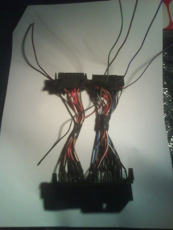
I used the socket connector off an old control module from another omega from the scrappers, and soldered the wires from the facelift loom cuts to the relevant pins on the socket. Order of things...
Pre-facelift loom -> Socket -> Through adaption loom -> Facelift Control Module
The wire in the top-left is from Pin 10 of the 12-way (boot release solenoid)
The 4 wires top-right are 3 for the ultrasonics & light, 1 for boot release switch
The single wire loose bottom-left is from pin 4 of the 28-pin connector, and will be soldered to pin 4 of the 12-way connector tomorrow.


 Author
Topic: Facelift & Pre-facelift central locking ecu's... (Read 10855 times)
Author
Topic: Facelift & Pre-facelift central locking ecu's... (Read 10855 times)