Central locking motor failures are a common and irritating problem. Whilst the motors are not too expensive on Trade Club they aren't exactly cheap either.
The majority of failures are actually caused by the failure of a microswitch inside the motor assembly (it's actually a motor, not a solenoid), and this is cheap and relatively easy to change.
Firstly, the motor must be removed from the car by following the appropriate maintenance guides:
http://www.omegaowners.com/forum/index.php?topic=90504.0http://www.omegaowners.com/forum/index.php?topic=90543.0Once the motor is on the bench the black plastic cover needs to be removed, as follows:
Ease the rubber seal around the actuating lever off the motor body and lever.
Pull the actuating lever out to the fully extended position and remove the protruding part of the white plastic lever from the section that extends into the motor body by sliding it sideways.
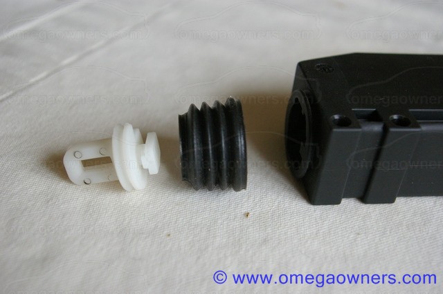
Punch out the 2 roll pins by the lower end of the motor body and carefully prise the black cover past the four lugs surrounding the roll pin holes and off the motor body.
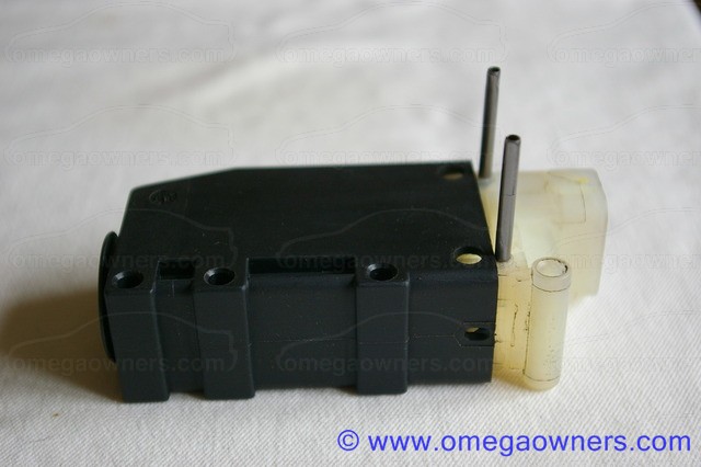
This is what you should see:
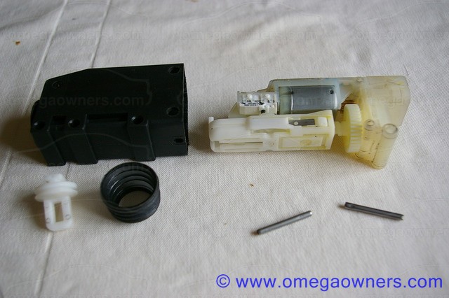
In the following picture you can see the silver motor in the centre with gearing to the left. To the right of the motor is the white microswitch that causes problems. Note that it may not always be white!
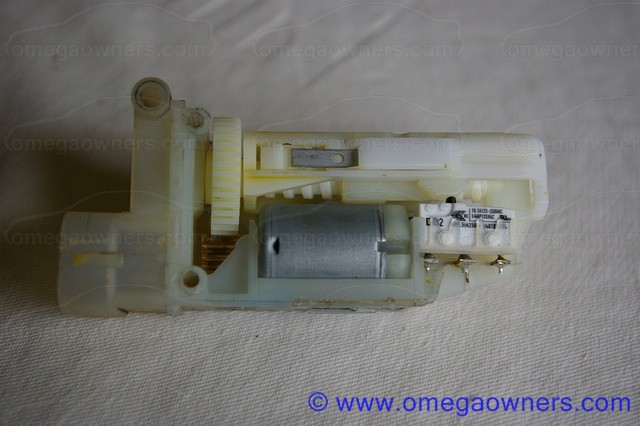
In the following picture the mechanism has been stripped down to show the two microswitches in position. Note that passenger and rear doors do not use the second (black in this case) microswitch, and it may not be fitted to the unit at all. The repair procedure is the same. however.
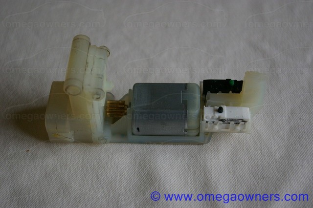
Here is the mechanism that was removed to show the microswitches. A rack is turned by the motor which winds a plastic sled up and down. This sled sits inside the internal part of the lock actuating lever.
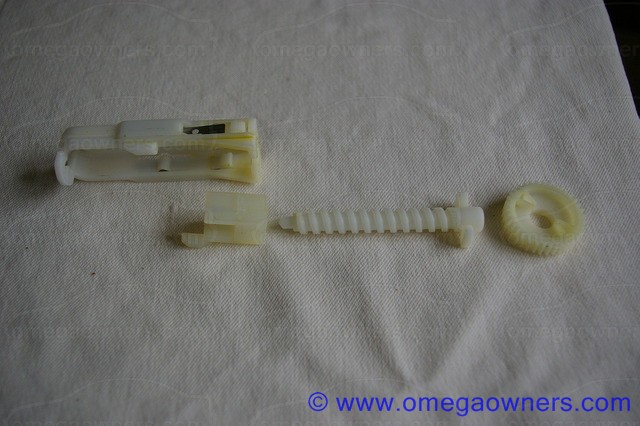
Here is the assembly as it sits inside the motor:
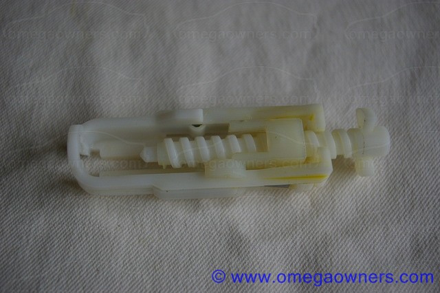
The sled has 3 positions:
It can be wound fully down towards the bottom of the motor whereby it will take the actuating lever down with it and lock the door.
It can be wound fully upwards, taking the actuating lever with it, and unlocking the door.
It can be at a central "parked" position where manual control of the actuating lever is possible, allowing the door to be unlocked and locked manually. When the car is deadlocked, the sled is parked in the fully downwards position, which makes it impossible to manually lift the actuating lever to unlock the door.
It is the microswitch which senses the central position of the sled which causes problems. The purpose of this switch is to cut the supply to the motor as the sled reaches the central position from either above or below. As it wears the contacts become intermittent, and then fail completely, meaning that the supply to the motor is disconnected and the door does not respond to the central locking system.
The microswitch can be tested with a multimeter in-situ at this stage, or one or both of the switches can be replaced as a matter of course. If the rest of the device looks clean, there is no evidence of water ingress or other damage and the mechanism moves freely, it is a fair bet that a microswitch failure caused the problem.
So, on to repairing the motor. To achieve this, the microswitch needs to be removed. It must be desoldered from the connections that are moulded into the body of the motor. The body material has a low melting point, so care must be taken in desoldering to ensure it is not damaged. You will need a desoldering iron or a fairly fine tipped soldering iron and desoldering pump to achieve this.
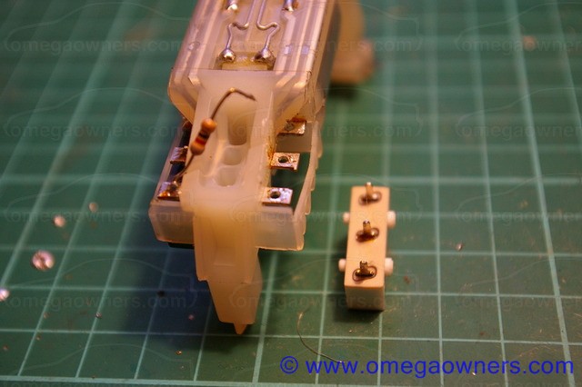
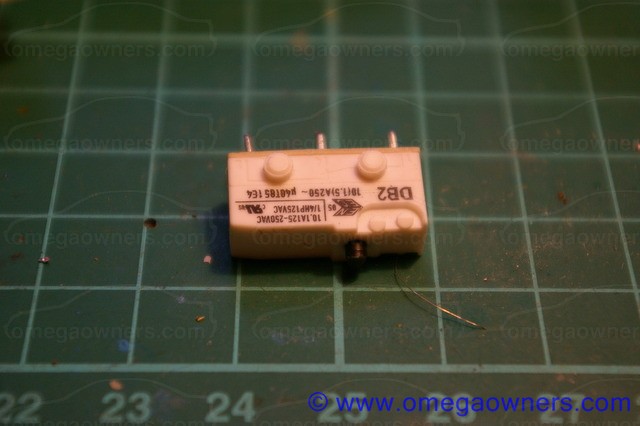
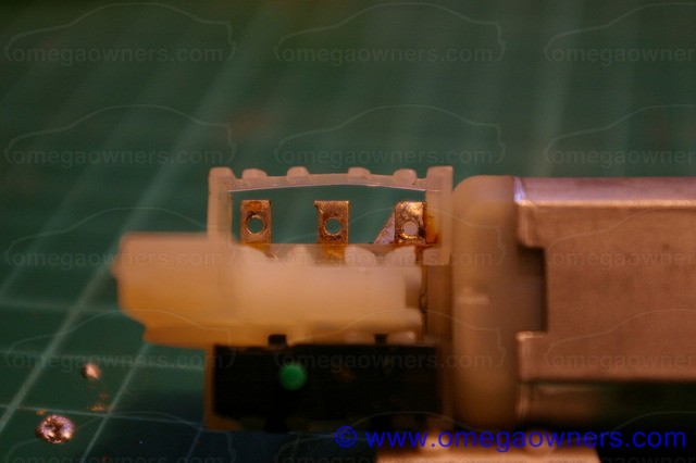
Once all of the pins have had the solder removed and are free in their holes, ease the body of the microswitch out of the plastic retaining moulding.
The microswitch is a Cherry type DB2 with button actuator and straight PCB pins (not the solder bucket connections).
RS part number 290-0463, £1.26 at the time of writing looks a direct replacement, as does Farnell part number 1519007, £1.38.
Similar pattern switches are available from Rapid components (78-2410 @ 47p). Note, however, that these do not have the high 10A current rating of the original Cherry switch so might well have a shorter life in this application!

 Author
Topic: Repairing a Central Locking Motor (Read 18601 times)

